Shows, Memories and Presets
178 APOLLO
Digital Broadcast Production Console
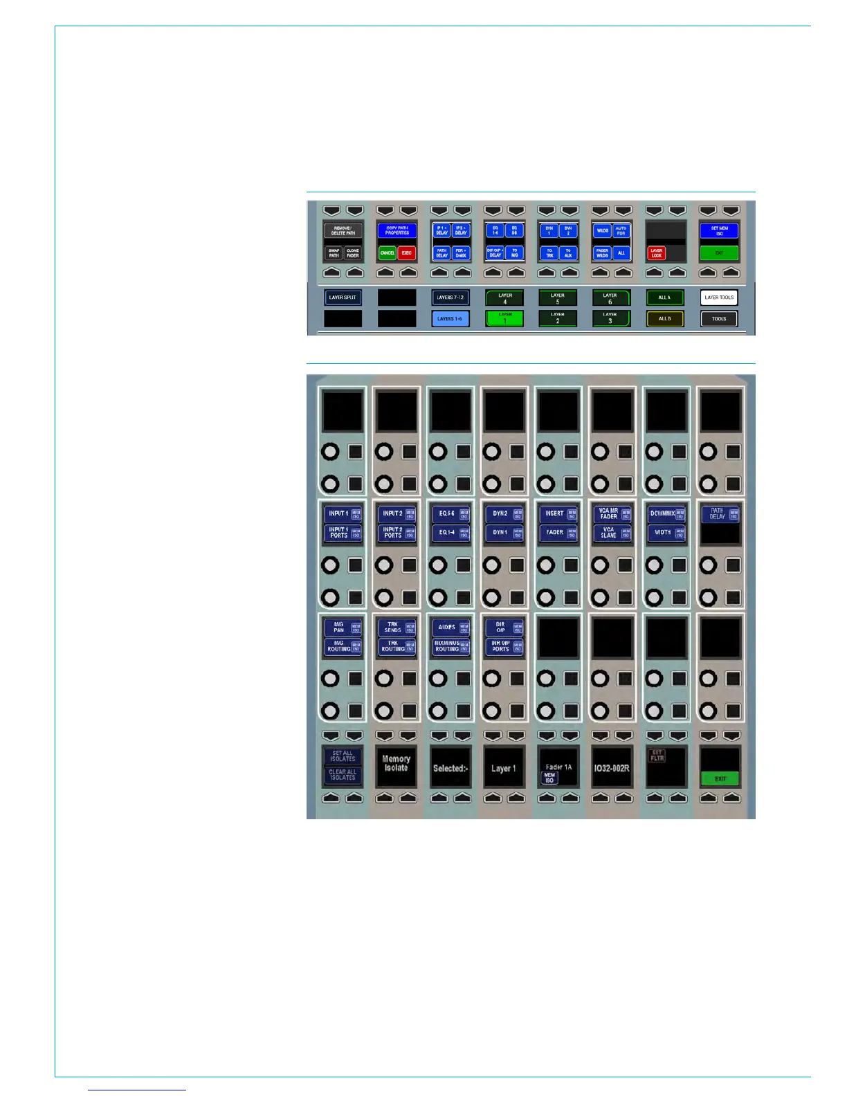
To set the scope, touch the LAYER
TOOLS button on the layers row. This
will update the row above as shown in
Fig 3. Now press the button above the
SET MEM ISO graphic on the modes row.
This will set the wild assign panel above
it into memory isolate mode as shown in
Fig 4 (apart from the mode title, the TFT
screen appears blank in this mode). On
entering this mode, the modes row and
layers row return to their default state and
the MEM ISO buttons are visible again.
The lower two rows of control cells on
the wild assign panel will now display the
elements of the path which can isolated.
They relate to the currently assigned path.
These elements may vary depending on
the type of path assigned, for example
input and input port settings are not
applicable to groups.
Press the relevant button to toggle
the elements which should be isolated
when the assigned path is isolated. The
selected elements will illuminate. The
SET ALL ISOLATES and CLEAR ALL
ISOLATES buttons in the button cells
below switch all elements on or off
respectively.
The PART ISO button in the button cells
toggles partial memory isolation on or
off for the assigned path. When a path
has been partially isolated, the button
cell above the fader on the fader panel
will show the green PART ISO indicator
instead of the fully isolated blue MEM ISO
indicator.
FIG 4 - MEMORY ISOLATE MODE
FIG 3 - ACCESSING THE SCOPE OF THE MEMORY ISOLATE FUNCTION