GR712RC-UM, Jun 2017, Version 2.9 142 www.cobham.com/gaisler
GR712RC
18.5.2 Mode register
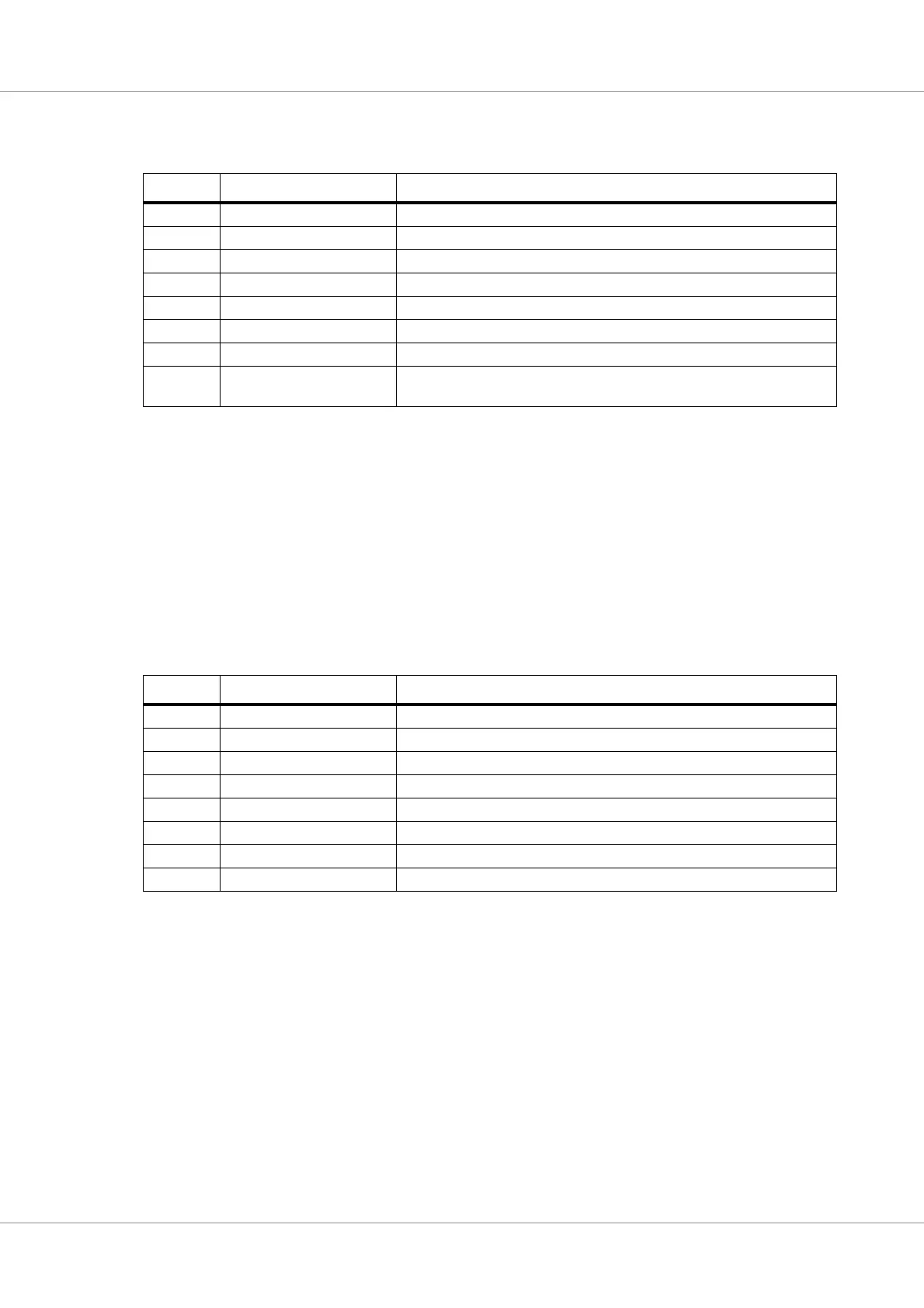
Table 128.Bit interpretation of mode register (MOD) (address 0)
Writing to MOD.1-3 can only be done when reset mode has been entered previously.
In Listen only mode the core will not send any acknowledgements. Note that unlike the SJA1000 the
Opencores core does not become error passive and active error frames are still sent!
When in Self test mode the core can complete a successful transmission without getting an acknowl-
edgement if given the Self reception request command. Note that the core must still be connected to a
real bus, it does not do an internal loopback.
18.5.3 Command register
Writing a one to the corresponding bit in this regist
er initiates an action supported by the core.
A transmission is started by writing 1 to CMR.0. It can only be aborted by writing 1 to CMR.1 and
only if the transfer has not yet started. Setting CMR.0 and CMR.1 simultaneously will result in a so
called single shot transfer, i.e. the core will not try to retransmit the message if not successful the first
time.
Giving the Release receive buffer command should be done after reading the contents of the receive
buffer in order to release this memory. If there is another message waiting in the FIFO a new receive
interrupt will be generated (if enabled) and the receive buffer status bit will be set again.
The Self reception request bit together with the self test mode makes it possible to do a self test of the
core without any other cores on the bus. A message will simultaneously be transmitted and received
and both receive and transmit interrupt will be generated.
Bit Name Description
MOD.7 - reserved
MOD.6 - reserved
MOD.5 - reserved
MOD.4 - not used (sleep mode in SJA1000)
MOD.3 Acceptance filter mode 1 - single filter mode, 0 - dual filter mode
MOD.2 Self test mode If set the controller is in self test mode
MOD.1 Listen only mode If set the controller is in listen only mode
MOD.0 Reset mode Writing 1 to this bit aborts any ongoing transfer and enters reset mode. Writ-
ing 0 returns to operating mode
Table 129.Bit interpretation of command register (CMR) (address 1)
Bit Name Description
CMR.7 - reserved
CMR.6 - reserved
CMR.5 - reserved
CMR.4 Self reception request Transmits and simultaneously receives a message
CMR.3 Clear data overrun Clears the data overrun status bit
CMR.2 Release receive buffer Free the current receive buffer for new reception
CMR.1 Abort transmission Aborts a not yet started transmission.
CMR.0 Transmission request Starts the transfer of the message in the TX buffer