GR712RC-UM, Jun 2017, Version 2.9 149 www.cobham.com/gaisler
GR712RC
RX identifier 2, EFF frame
Bit 7:0 - Bit 20 downto 13 of 29 bit EFF identifier.
RX identifier 3, EFF frame
Bit 7:0 - Bit 12 downto 5 of 29 bit EFF identifier.
RX identifier 4, EFF frame
Bit 7:3 - Bit 4 downto 0 of 29 bit EFF identifier
Bit 2- 1 if RTR frame
Bit 1:0 - Don’t care
Data field
For received SFF frames the data field is located at address 19 to 26 and for EFF frames at 21 to 28.
18.5.14 Acceptance filter
The acceptance filter can be used to filter out messages not meeting certain demands. If a message is
filtered out it will not be put into the receive fifo and the CPU will not have to deal with it.
There are two different filtering modes, single and dual filter. Which one is used is controlled by bit 3
in the mode register. In single filter mode only one 4 byte filter is used. In dual filter two smaller fil-
ters are used and if either of these signals a match the message is accepted. Each filter consists of two
parts the acceptance code and the acceptance mask. The code registers are used for specifying the pat-
tern to match and the mask registers specify don’t care bits. In total eight registers are used for the
acceptance filter as shown in the table below. Note that they are only read/writable in reset mode.
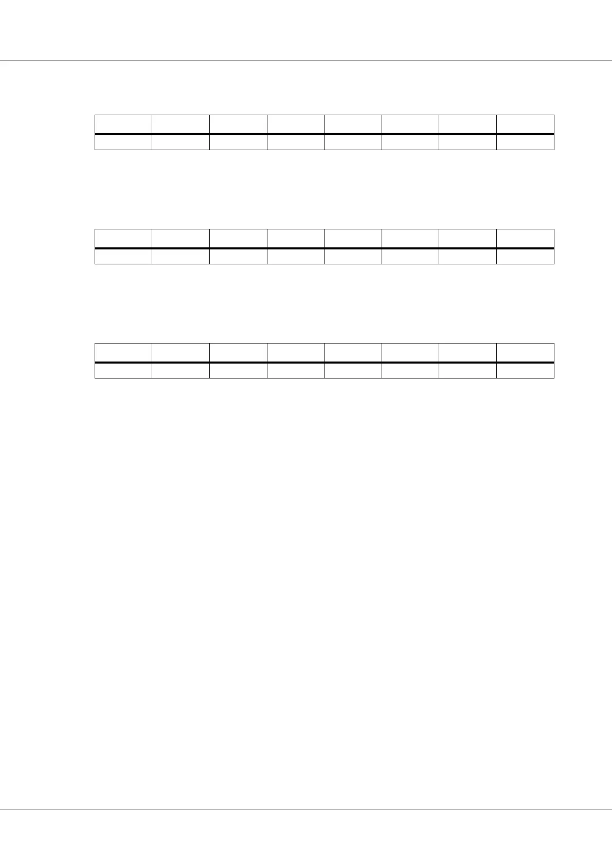
Table 148.RX identifier 2 address 18
Bit 7 Bit 6 Bit 5 Bit 4 Bit 3 Bit 2 Bit 1 Bit 0
ID.20 ID.19 ID.18 ID.17 ID.16 ID.15 ID.14 ID.13
Table 149.RX identifier 3 address 19
Bit 7 Bit 6 Bit 5 Bit 4 Bit 3 Bit 2 Bit 1 Bit 0
ID.12 ID.11 ID.10 ID.9 ID.8 ID.7 ID.6 ID.5
Table 150.RX identifier 4 address 20
Bit 7 Bit 6 Bit 5 Bit 4 Bit 3 Bit 2 Bit 1 Bit 0
ID.4 ID.3 ID.2 ID.1 ID.0 RTR 0 0