InteliDrive Lite, SW version 1.9
ID-FLX-Lite-1.9r1 Reference Guide.pdf, ©ComAp – August 2015
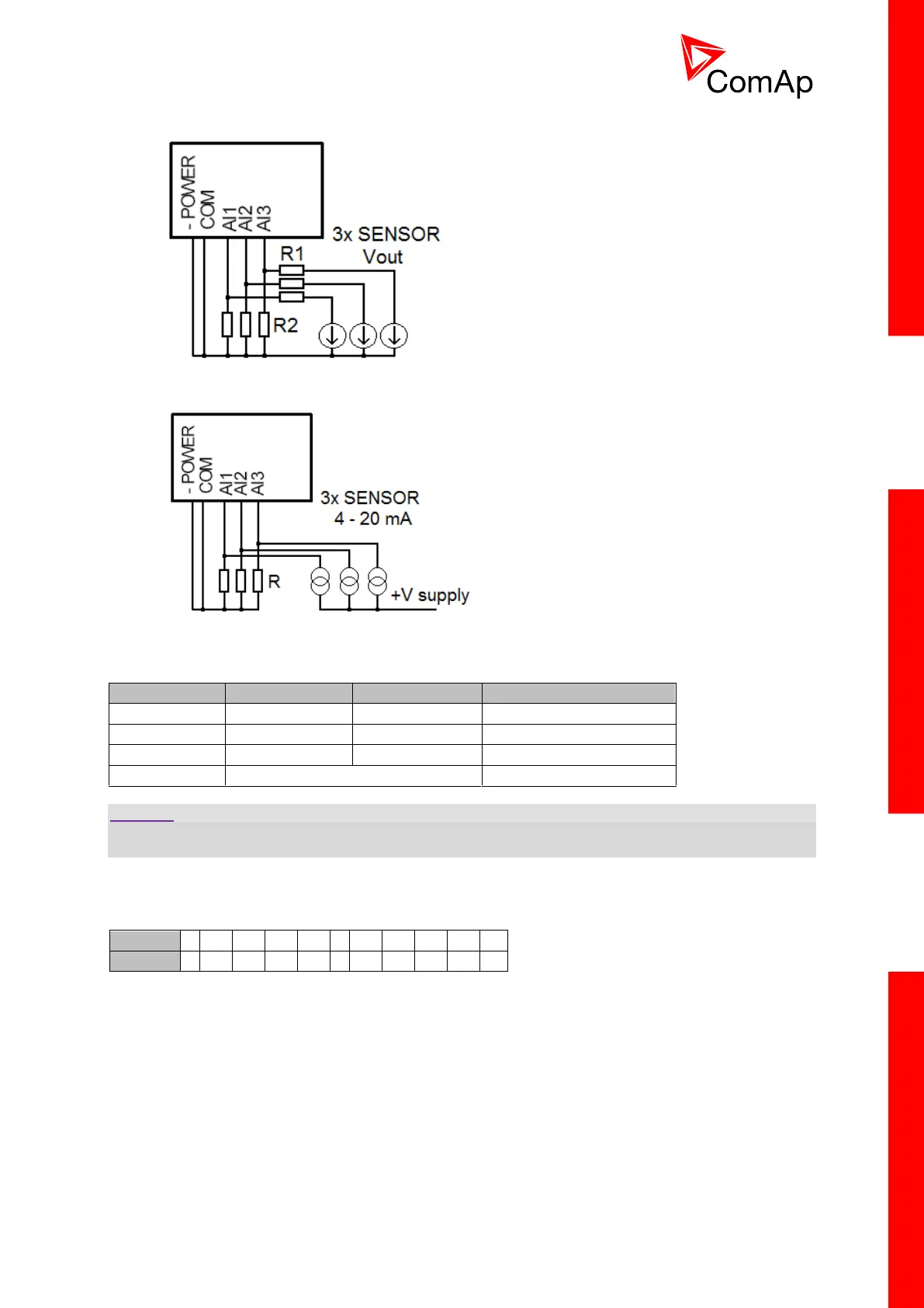
Voltage output sensor - connection
Current output sensor – connection
Table with recommended values
CAUTION!
Please note that external resistors disconnection, connection incorrect resistors or input voltage value
during operation may cause an analog input destruction.
Practical example: VDO pressure sensor 0 – 6bar with linear voltage output 0 – 10V
Conversion table
Modify one of analog input in LiteEdit configuration and load curve AI 0-10V.CRV
Than you can change resolution and measured value name witch is default displayed at V (volts).
For example if you have connected pressure sensor and his output voltage is 5V for pressure 3bar
you can change value ‘V’ in column “Dim:” to ‘Bar’ and by sensor specification adjust all corresponding
values in this column. In this case you can change the value at row 6. from 5 to 3.