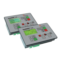
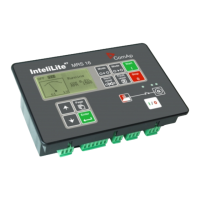
InteliDrive Lite, SW version 1.9
ID-FLX-Lite-1.9r1 Reference Guide.pdf, ©ComAp – August 2015
HINT
When LBI Nominal/Idle is configured (to a physical binary input), it has priority and the
switching between the nominal and the idle speed by I/0 button is blocked.
Conveyor: Initial condition: Running engine. Press I/0 button activates BO Horn. After the horn
signal, the BO Conveyor is activated.
RegReqst: Switches between setpoints Request 1 and Request 2 as requested value input for
regulator.
R RegDis: In AUT mode, switching the I/0 button allows or disable the PI regulation to work.
When the regulation is blocked, the regulator analog output is set according to the
constant Regulator: Reg bias.
CloseLoad: When the engine is in the status Ready to Load, this option switches ON and OFF the
LBO Close Load. When the engine is not in the status Ready to Load, the button has
no influence.
NOTE:
The applications without the information about the speed can not reach the status
Ready to Load and therefore, the load can not be switched by the I/O button. That’s
why, in the case of settings: SP Gear teeth = 0, SP RPM source = PickUp, no ECU,
the condition sufficient for LBO Close Load activating by the I/O button is the Running
state.
Toggle: Switches ON and OFF the LBO Toggle, no other consequences.
7.2.11 RunHoursSource [ECU, INTERNAL, AUTO]
This setpoint is used for adjustment of RunHours source of the engine.
ECU: RunHours are all the time read from ECU.
INTERNAL: RunHours are counted from the inner counter of the controller.
AUTO: If is coming from ECU rational value higher than 0, then the RunHours are taken from
ECU, in second case are displayed internal hours from controller. Default state.
CAUTION!
Some types of ECUs reset RunHours counter to 0, if the supply was disconnected.
7.2.12 Main Screen [SHOW TIMERS, SHOW AIN]
Change the display of the main Measurment screen.
SHOW TIMERS: Standard display with timers on the left side of the screen. Default state.
SHOW AIN: Instead of timers are on the left side of the screen displayed values of analog
inputs AIN6 and AIN7.
7.3 Comms Settings
7.3.1 ControllerAddr [-]
It is controller’s identification number. It is possible to set controller address different from the default
value 1 so that more InteliDrive Lite controllers can be interconnected (via RS485) and accessed e.g.
from Modbus terminal.
Adresses: 1 - 32
 Loading...
