CDM-840 Remote Router MN-CDM840
Introduction Revision 3
1–6
1.3.3 Physical Features
1.3.3.1 Front Panel Features
• Chapter 2. INSTALLATION
• Chapter 7. ETHERNET-BASED REMOTE PRODUCT MANAGEMENT
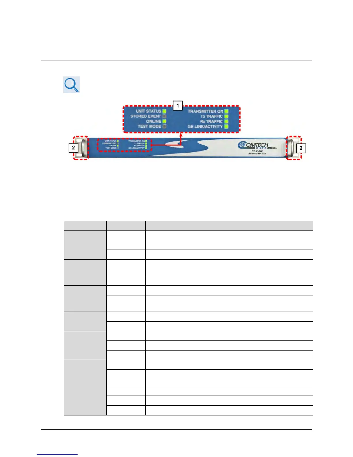
Figure 1-4. CDM-840 – Front Panel View
The CDM-840 front panel (Figure 1-4) provides these features:
1 LED Indicators
The front panel features eight (8) Light-Emitting Diode (LED) indicators. These LEDs convey
operational states as follows:
UNIT STATUS
No Unit Faults or Alarms.
No Unit Faults, but an Alarm exists.
A Unit Fault exists (Example: PSU fault).
STORED
EVENT
Amber
There is a Stored Event in the log, which can be viewed from the HTTP
Interface
Off There are no Stored Events.
ONLINE
The Unit is On Line, and carrying traffic.
Off
The Unit is Off Line (standby) – forced by externally connected 1:1 or 1:N
redundancy system.
TEST MODE
There is no Test Mode currently selected.
TRANSMITTER
ON
The Transmitter Carrier is On.
A Fault exists that causes the unit to turn off the carrier.
The Transmitter Carrier is Off.
Tx TRAFFIC
No Tx Traffic Faults, no packets.
No Tx Traffic Faults, blinks when a packet is being transmitted to the satellite
link from this unit.
A Tx Traffic Alarm exists.