CDM-840 Remote Router MN-CDM840
Rear Panel Connections Revision 3
3–5
3.2 CDM-840 Cabling Connections
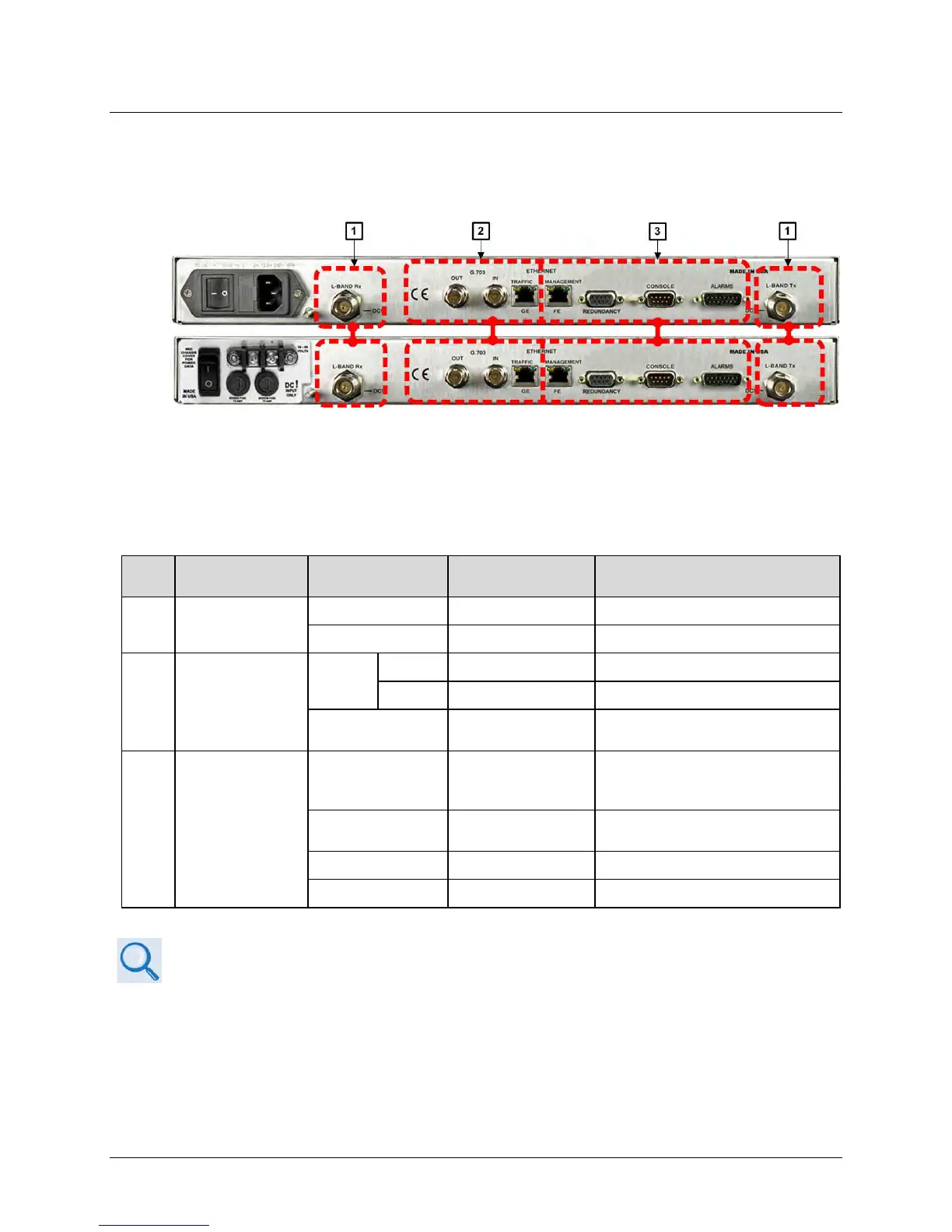
The CDM-840 rear panel connectors, shown here in Figure 3-3 provide all necessary external
connections between the unit and other equipment.
(TOP) Standard AC Unit
(BOTTOM) Optional -48V DC Unit
Figure 3-3. CDM-840 Cabling Connections
Table 3-1 summarizes the available connectors, grouped according to service function.
Table 3-1. CDM-840 Rear Panel Connectors
Group Name
(Chapter Sect.)
Connector Name Connector Type Connector Function
1
IF Connector Group
(3.2.1)
L-BAND Rx 50Ω Type ‘N’ female L-Band Input
L-BAND Tx 50Ω Type ‘N’ female L-Band Output
2
Terrestrial Data
Connector Group
(3.2.2)
G.703
OUT BNC female G.703 E1 Output
IN BNC female G.703 E1 Input
RJ-45 female
10/100/1000 BaseT Gigabit Ethernet
interface (IEEE 802.3ab)
3
Utility Connector
Group (3.2.3)
ETHERNET |
MANAGEMENT | FE
RJ-45 female
10/100 BaseT Fast Ethernet
management/data interface (IEEE
REDUNDANCY
9-pin Type ‘D’ female
For connection to an optional 1:1 or
1”N CEFD Redundancy Switch
9-pin Type ‘D’ male
EIA-232 Serial Remote Interface
15-pin Type ‘D’ male
See Sect. 3.1 Overview – Cabling Connections Types for information about each connector
type and its connection instructions.