CDM-840 Remote Router MN-CDM840
Appendix C Revision 3
C–7
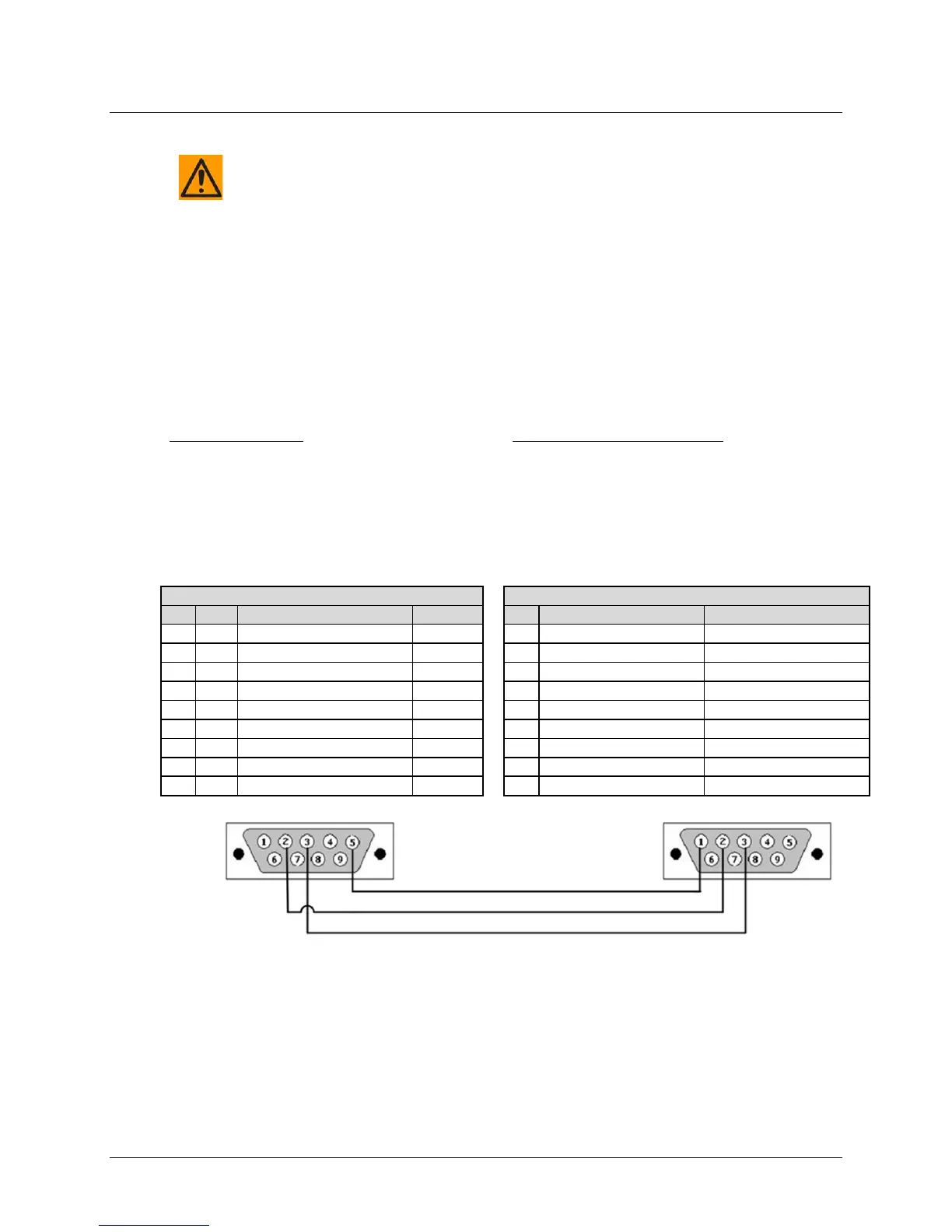
C.5 Serial Adapter Cable Fabrication Specifications Reference
CAUTION – The European EMC Directive (EN55022, EN50082-1) requires using
properly shielded cables for DATA I/O. To ensure proper operation, fabrication of
this Serial Adapter Cable requires that :
• You must wire the connectors using the pinout tables and diagram provided
here.
• Type 'D' connectors must have back-shells with continuous metallic shielding.
• Type ‘D’ cabling must have a continuous outer shield (either foil or braid, or
both). The shield must be bonded to the connector back-shells.
Description: PC Serial Port Interface
Cable Connector Type: D-Subminiature DB-9F
(Type D-Sub 9-pin Female)
Use: For connection to your User PC RS-232 Serial
Port
Description: CDM-840 “CONSOLE” Port Interface
CDM-840 Onsite Unit Interface End
Cable Connector Type: D-Subminiature DB-9M
(Type D-Sub 9-pin Male)
Use: For connection to the CDM-840 Onsite Unit
“CONSOLE” Port