CDM-840 Remote Router MN-CDM840
Introduction Revision 3
1–7
Rx TRAFFIC
No Rx Traffic Faults (demod and decoder are locked, everything is OK).
No Rx Traffic Faults, blinks when a packet is being received from the satellite
link to this unit.
GE
LINK/ACTIVITY
Traffic Ethernet is connected, but no traffic exists.
Ethernet activity detected.
Off Traffic Ethernet is not connected.
2 Rack Handles
In a rack enclosure, these handles help you install and remove the unit.
1.3.3.2 Rear Panel Features
• Sect. 3.2 CDM-840 Cabling Connections
• Sect. 3.3 CDM-840 Ground and Power Connections
CAUTION – PROPER GROUNDING PROTECTION IS REQUIRED. The equipment must be
connected to the protective earth connection at all times. It is therefore imperative that
the unit is properly grounded, using the ground stud provided on the unit rear panel,
during installation, configuration, and operation.
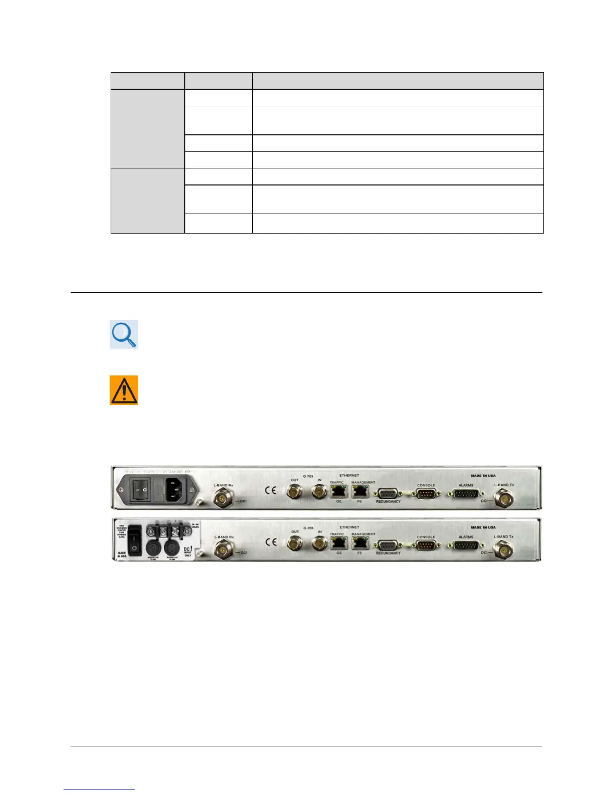
External cables are attached to connectors provided on the rear panel of the unit (Figure 1-5).
(TOP) Standard AC Unit
(BOTTOM) Optional 48V DC
Figure 1-5. CDM-840 – Rear Panel View