CDM-570A/570AL Satellite Modem with Optional Packet Processor
Revision 5
Introduction 1–7 MN-CDM570A
1.2.3.2 Rear Panel Features
• Chapter 2. INSTALLATION
• Chapter 3. REAR PANEL CONNECTIONS
CAUTION – CORRECT GROUNDING PROTECTION IS REQUIRED TO PREVENT
PERSONAL INJURY AND EQUIPMENT DAMAGE. You must make sure the ground
stud on the rear panel of the modem is always connected to the protective earth.
External cables are attached to connectors provided on the rear panel of the modem
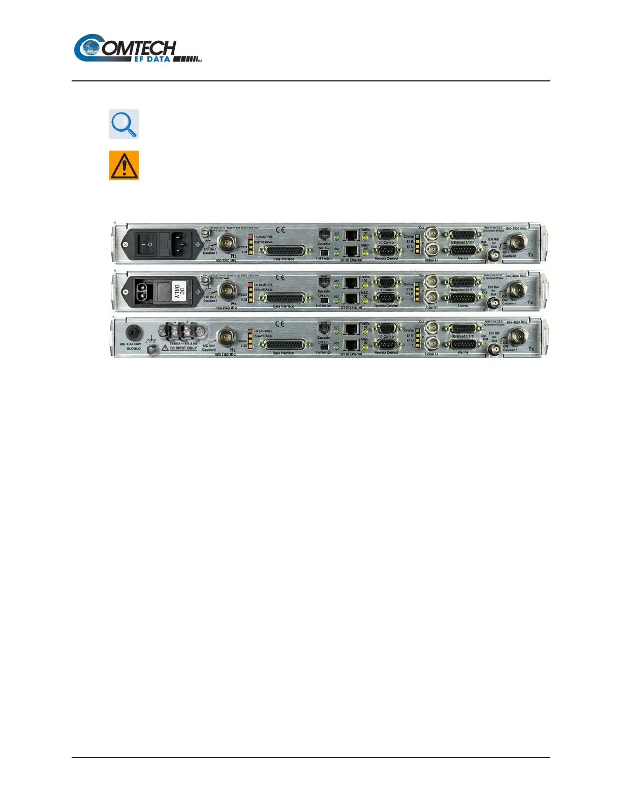
(TOP) Standard AC Chassis
(MIDDLE) Optional -24V or -48V DC Chassis
(BOTTOM) CDMR-570AL Reduced Chassis Depth Modem -24V or -48V DC Chassis
Figure 1-4. Modem Rear Panel View (Shown w/Optional Packet Processor)
1.2.3.2.1 Rear Panel Standard Features
As per Figure 1-4, from left to right:
Power Interface:
• For the CDM-570A/570AL – 100V to 240V AC Primary Input Power Supply with Press-fit
Fuse Holder.
• For the CDMR-570AL – -24V or -48V DC Primary Input Power Supply with Screw-in
Fuse Holder.
IF Interfaces:
• For the CDM-570AL or CDMR-570AL – (2X) Type ‘N’ female “Rx” (at far left) and “Tx”
(at far right) connectors for 50Ω L-Band (950 to 2250 MHz) operation.
• For the CDM-570A – (2X) BNC female “Rx” (at far left) and “Tx” (at far right) connectors
for 70/140 MHz operation.