CDM-570A/570AL Satellite Modem with Optional Packet Processor
Revision 5
Rear Panel Connectors and Pinouts 3–11 MN-CDM570A
3.2.3 Utility Connections Group
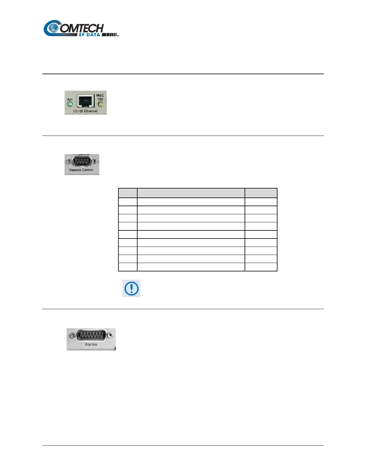
3.2.3.1 10/100 Ethernet | M&C 100 Port, RJ-45 (Standard)
This 8-pin RJ-45 modular port is present on the base modem assembly. Use a
CAT5 cable to connect this port to an Ethernet hub, router, switch, PC, etc. for
M&C purposes and to update the base modem firmware.
See Table 3-3
for the typical port pinouts.
3.2.3.2 Remote Control Connector, DB-9M
Use this 9-pin type ‘D’ male (DB-9M) connector to connect the modem to an M&C
computer, or terminal device. This interface is user-selectable for either EIA-232 or
EIA-485.
Table 3-5. Remote Control Connector Pin Assignments
Reserved - do not connect to this pin
**Use for EIA-485 2-Wire operation
3.2.3.3 Alarms (Form-C Traffic Alarms) Connector, DB-15M
Use this 15-pin type 'D' male (DB-15M) connector to provide user access to
the Form-C relay contacts that indicate the unit alarms/fault status. These
contacts typically connect to the external fault monitoring system often
found in satellite earth stations.
This connector also provides:
• The receive ‘I’ and ‘Q’ demodulator samples. Connecting these signals to an oscilloscope
in X,Y mode will provide the receive signal constellation diagram, which is a useful
diagnostic aid.
• A pin that can mute the transmit carrier; this requires that the pin be shorted to ground or
a TTL ‘low’, or that an EIA-232 ‘high’ signal be applied.
• An analog AGC signal (Pin 2) as an aid to antenna pointing or for driving step-track
equipment.