CDM-570A/570AL Satellite Modem with Optional Packet Processor
Revision 5
Rear Panel Connectors and Pinouts 3–5 MN-CDM570A
3.2 Modem Cabling Connections
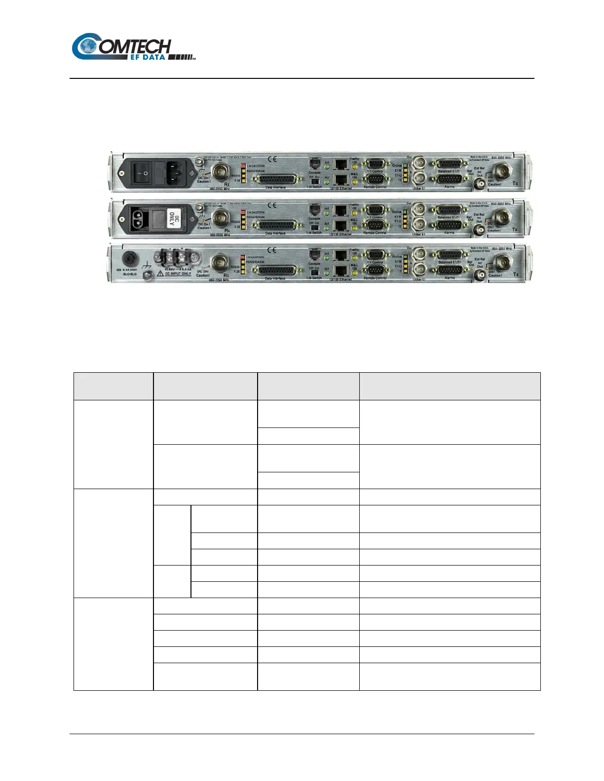
The modem rear panel connectors, shown here in 0H0HFigure 3-1 and summarized in Table 3-1,
provide all necessary external connections between the modem and other equipment. See
Sect. 3.3 for information about the modem’s power and ground connections.
(TOP) Standard AC Chassis
(MIDDLE) Optional -24V or -48V DC Chassis
(BOTTOM) CDMR-570AL Reduced Chassis Depth Modem -24V or -48V DC Chassis
Figure 3-3. Modem Rear Panel (CDM-570AL-IP Shown)
Table 3-1. Rear Panel External Cabling Connections
Connector Group
(Sect. Ref.)
Name Connector Type Function
(Sect. 3.2.1)
Rx
CDM-570AL/CDMR-
570AL: Type ’N’ female
IF Input
Tx
CDM-570AL/CDMR-
560AL: Type ’N’ female
IF Output
(Sect. 3.2.2)
Serial synchronous data Input/Output
G.703
Data
Balanced 15-pin Type ‘D’ female
G.703
T1 (1544 kbps) / E1 (2048 kbps)
Receive G.703 E1 (2048 kbps)
Transmit G.703 E1 (2048 kbps)
10/100
Ethernet
10/100 BaseT management and data
(w/optional Packet Processor) Ethernet Traffic
(Sect. 3.2.3)
Serial Remote Interface (EIA-232/-485)
Form C Alarms (relay closures)
Connection to External 1:1 Controller
Console RJ-11 female
(w/optional Packet Processor) EIA-232 Serial
Console for Packet Processor management