CDM-570A/570AL Satellite Modem with Optional Packet Processor
Revision 5
1:1 IP Redundancy N–10 MN-CDM570A
N.6 Cabling the CDM-570A-IP
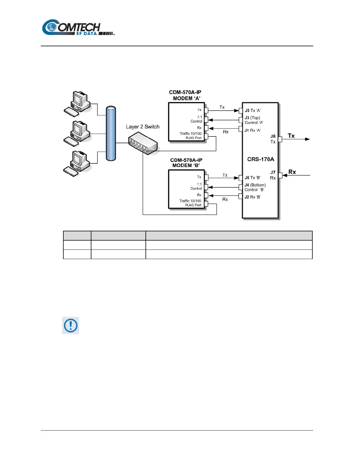
Figure N-4 shows connections of a pair of CDM-570A-IP s to the CRS-180 70/140 MHz 1:1
Redundancy Switch. The table provided here lists cable assemblies that may be supplied with the
CRS-180.
Control Cable, Universal, DB9 Male to Male, 4’
IF (Tx/Rx) Coax Cable, 50Ω Type ‘BNC’, 4’
Figure N-4. CDM-570A-IP and CRS-180 Interconnect
It is essential that you correctly make the control and Rx/Tx IF cable connections. For example,
the Tx IF from Modem ‘A’ connects to the Tx IF port ‘A’ on the CRS-180, and Modem ‘B’ connects
to the Tx IF Port ‘B’ (and the same for the Rx IF connections). Failure to observe this cabling
requirement will result in system malfunction.
When connecting the control cables between the CRS-180 and the modems,
make sure that the screw locks on the Type ‘D’ connectors are securely
fastened. This prevents the accidental unmating of the cable, particularly if a
standby unit must be removed or replaced.