CDM-570A/570AL Satellite Modem with Optional Packet Processor
Revision 5
Adaptive Coding and Modulation (ACM) Option P–8 MN-CDM570A
P.6 VersaFEC ACM (IP-ACM)
Appendix B.6. FEC (FORWARD ERROR CORRECTION) OPTIONS
P.6.1 VersaFEC ACM Latency
In an ACM system that has a number of ModCods, each having a different latency, what defines
the overall system latency? The answer is simple – the latency of the worst-case ModCod. (This
may not seem obvious to some, and it is beyond the scope of this chapter to provide a rigorous
defense of this statement. It is, however, a correct statement despite certain believers in non-
causal systems and encoders that possess the magical quality of negative latency…)
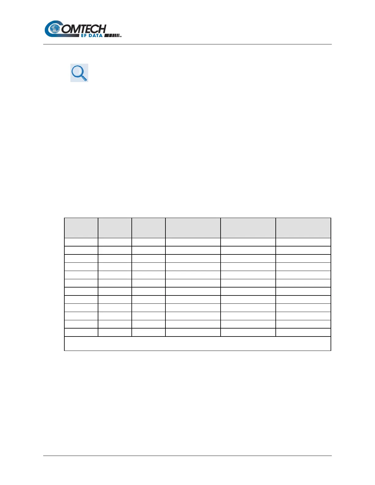
Examining the data in Table P-1, latency for each ModCod is shown for the example of
VersaFEC ACM at a fixed 100 ksymbols/second rate. Of particular note is that even though the
ModCods span a 7:1 variation in throughput, the latency is only varying between 25 and 34
milliseconds. A careful analysis will show that this is a consequence of using a constant number
of symbols per block. In the example shown the worst-case latency for this ACM scheme is 34
milliseconds, + WAN Buffer delay (which is configurable, with a minimum value of 20ms).
Table P-1. VersaFEC Implementation of ACM – 100 ksymbols/sec Example Case
ModCod Modulation Code Rate
Spectral efficiency,
bps/Hz
Bit rate (throughput)
In milliseconds,
OVERALL SYSTEM LATENCY = Worst-case ModCod (ModCod0)
Latency = 34 milliseconds + WAN Buffer delay
By way of comparison, consider the same 100 ksymbols/second rate, but this time using DVB-S2. It
becomes clear that there is an unintended penalty (besides demodulator complexity) to having a
constant number of bits per block. Each time the ModCod is lowered and the throughput is
reduced, the latency grows accordingly due to the block size being related to data rate, not symbol
rate.