CDM-570A/570AL Satellite Modem with Optional Packet Processor
Revision 5
Rear Panel Connectors and Pinouts 3–12 MN-CDM570A
Table 3-6. Alarms Connector Pin Assignments
AGC Voltage (Rx signal level, 0 to 10 volts)
Rx Q Channel (Constellation monitor)
Rx I Channel (Constellation monitor)
Unit Fault (Energized, No Fault)
Unit Fault (De-energized, Faulted)
Tx Traffic (Energized, No Fault)
Tx Traffic (De-energized, Faulted)
Rx Traffic (Energized, No Fault)
Rx Traffic (De-energized, Faulted)
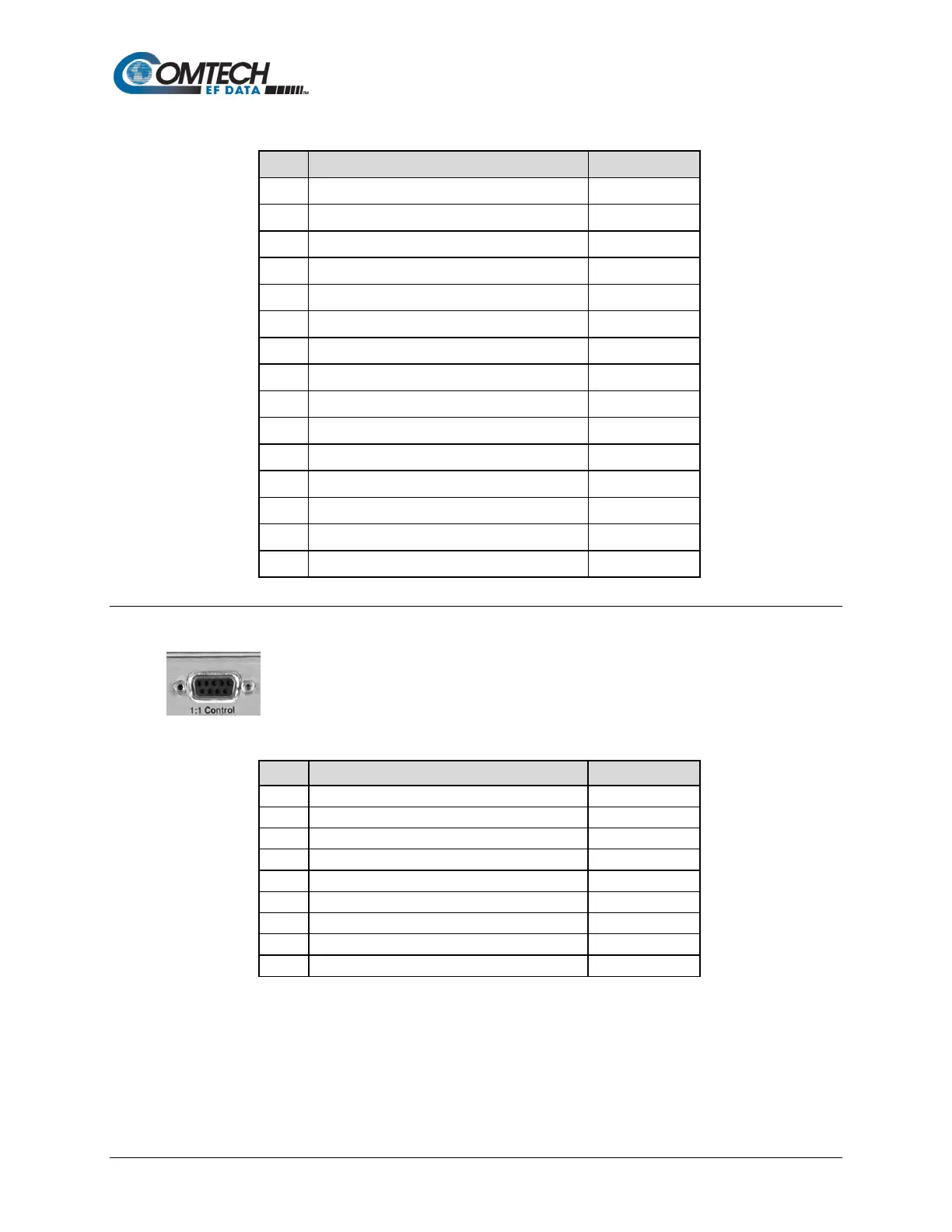
3.2.3.4 1:1 Control Connector, DB-9F
Use this 9-pin type ‘D’ female connector (DB-9F) to connect the modem only to
a CRS-170A (L-Band) or CRS-180 (70/140 MHz) switch in 1:1 redundancy
configurations.
Table 3-7. 1:1 Control Connector Pin Assignments
Receive Serial Data – auxiliary channel
Transmit Serial Data – auxiliary channel