Appendix E Revision 4
CDM-760 Advanced High-Speed Trunking Modem MN-CDM760
E–2
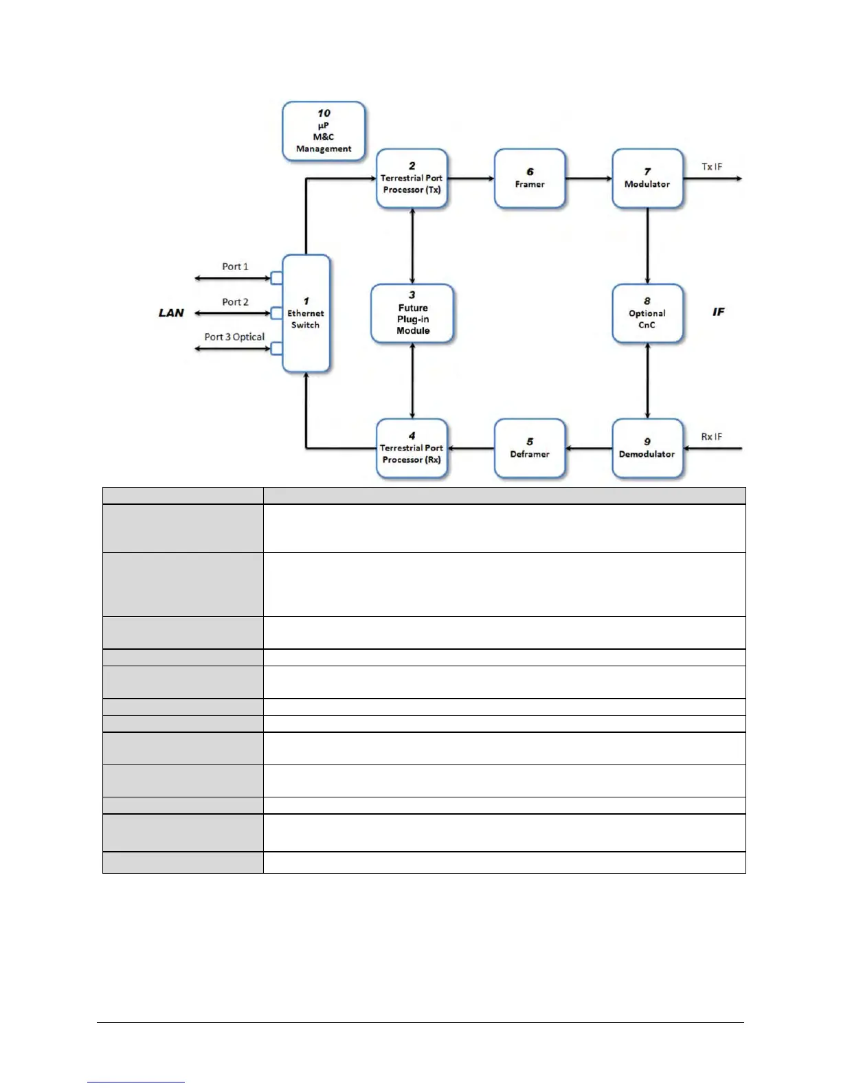
LAN Region
This unmarked region of the diagram refers to the LAN – the source / destination for data traffic.
The information of interest is tailored to Ethernet interfaces, so most of the statistics do not apply
Block 1 – Ethernet Switch
The LAN’s access to the modem is at the Ethernet switch. There are two RJ-45
10/100/1000BaseT ports (Port 1 – J5 | DATA / GBEI1, and Port 2 – J6 | DATA / GBEI2) and one
optional optical Gigabit Ethernet (SFP module) port (Port 3 – J7 | OPTICAL) available at the rear
Block 2 – Terrestrial Port
Processor (Tx)
Data from the LAN destined to the satellite flows into this block.
This is reserved for future plug-in modules.
Block 4 – Terrestrial Port
Processor (Rx)
This is the counterpart to the Tx processor. It forms Ethernet packets and forwards them to the
Ethernet Switch.
The data from the satellite frames is recovered.
Data processing to assemble data into frames for the modulator is performed in this block.
Block 7 – Modulator
Frames are mapped into the appropriate FECFrame and mapped into the selected ModCod for
transmission to the satellite.
Block 8 – CnC
Signals to and from the satellite are processed here to cancel the locally transmitted carrier and
receive the carrier from the distant end.
Carriers received from the satellite are processed here to recover data frames.
Block 10 – µP / M&C /
Management
The microcontroller (µP) is involved in collection and calculation of statistics.
IF Region This unmarked region of the diagram refers to data to or from the satellite link.
Figure E-1. CDM-760 Data Flow Diagram