Introduction Revision 4
CDM-760 Advanced High-Speed Trunking Modem MN-CDM760
1–6
1.2.3.2 Rear Panel Features
• Chapter 2. INSTALLATION
• Chapter 3. REAR PANEL CONNECTIONS
CORRECT GROUNDING PROTECTION IS REQUIRED TO PREVENT PERSONAL INJURY AND
EQUIPMENT DAMAGE. You must make sure the ground stud on the rear panel of the unit
is always connected to the protective earth.
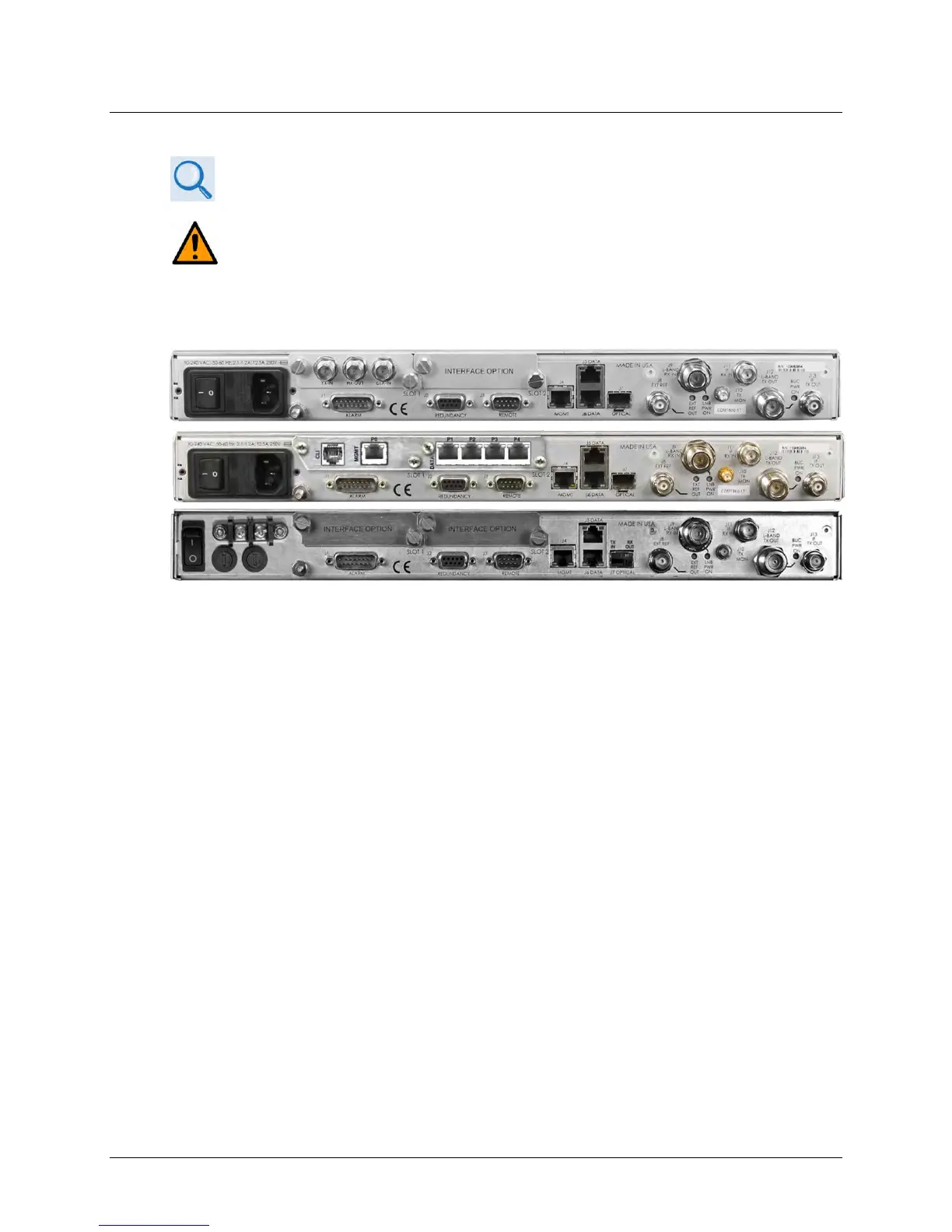
External cables are attached to connectors provided on the rear panel of the unit (Figure 1-4).
(TOP) Standard AC Unit (w/optional PIIC)
(MIDDLE) AC Unit (w/optional High-Speed Packet Processor)
(BOTTOM) Optional 48V DC Unit
Figure 1-4. CDM-760 Rear Panel View
1.2.3.2.1 Rear Panel Standard Features
Utility and Traffic Data Interfaces:
• (1X) J1|ALARM DB-15M connector for Form C unit alarms, analog Es/No, and Tx Mute.
• (1X) J3|REMOTE DB-9F ‘EIA-232 connector for serial remote control:
• (1X) J4|MGMT 10/100/1000 BaseT Fast Ethernet RJ-45 Interface for Ethernet-based
management and control purposes (HTTP/Web and SNMP).
• (2X) J5|DATA and J6|DATA 10/100/1000 BaseT Gigabit Ethernet RJ-45 Interface ports for
Ethernet traffic.
• (1X) J8 | EXT REF Type ‘BNC’ female input/output connector for supply of a master
reference to the modem.
IF Interfaces:
• (2X) J9 | L-BAND RX IN and J12 | L-BAND TX OUT Type ‘N’ female connectors for 50Ω
L-Band (950 to 2150 MHz) input/output.
• (2X) J11 | IF RX IN and J13 | IF TX OUT Type ‘BNC’ female connectors for 75Ω (standard) or
50Ω (optional) 70/140 MHz input/output.
• (1X) J10 | TX MON Type ‘SMA’ female connector for L-Band signal user monitor output.
Power Interface: