Rear Panel Connections Revision 4
CDM-760 Advanced High-Speed Trunking Modem MN-CDM760
3–5
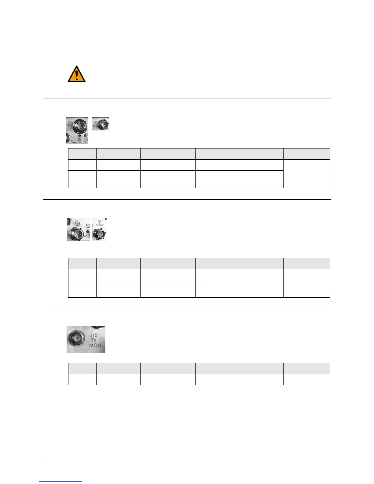
3.2.1 IF Connector Group
CAUTION
THERE MAY BE DC VOLTAGES PRESENT ON THE TYPE ‘N’ RX AND TX IF CONNECTORS,
UP TO A MAXIMUM OF 48 VOLTS.
3.2.1.1 Rx Connectors
The J9 | L-BAND RX IN Type ‘N’ connector features an LED labeled “LNB PWR
ON”. When a Low-Noise Block Down Converter (LNB) is installed in an L-Band
configuration, the LED lights amber to indicate the presence of DC voltage.
J9 L-BAND RX IN Type ‘N’ female Rx IF signal, L-Band
I
J11 IF RX IN BNC
Rx IF signal, 70/140 MHz band
Note: 75Ω default, 50Ω optional
3.2.1.2 Tx Connectors
The J12 | L-BAND TX OUT Type ‘N’ connector features an LED labeled “BUC
PWR ON”. Reserved for FUTURE use: When a Block Up Converter (BUC) is
installed in an L-Band configuration, the LED glows amber to show the presence
of DC voltage.
Type ‘N’ female Tx IF signal, L- band
O
J13 IF TX OUT BNC
Tx IF signal, 70/140 MHz band
Note: 75Ω default, 50Ω optional
3.2.1.3 J10 | TX MON Connector, Type ‘SMA’
The Type ‘SMA’ female J10 | TX MON connector provides a user monitor
output for the L-Band signal.
Ref Des Name Connector Type Description Direction (I/O)
J10 TX MON Type ‘SMA’ female Monitor L-Band Tx IF Output O