Rear Panel Connections Revision 4
CDM-760 Advanced High-Speed Trunking Modem MN-CDM760
3–6
3.2.2 Utility Connector Group
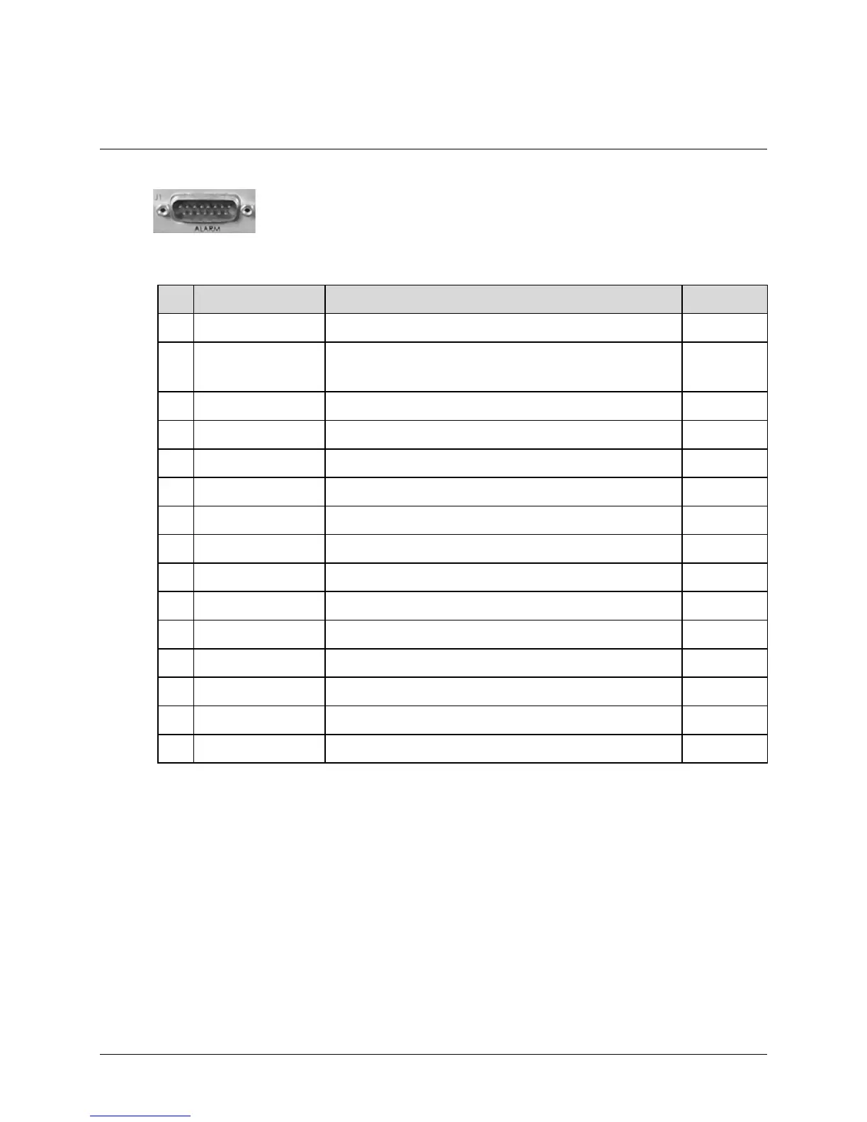
3.2.2.1 J1 | ALARM Connector, DB-15M
The J1 | ALARM 15-pin Type ‘D’ male (DB-15M) connector provides the unit
alarms interface.
The connector pinouts are as follows:
Pin # Name Signal Function Direction (I/O)
1 GND Ground Gnd
9 EXT-OFF
Ext Carrier Off, active low.
Capability to mute modem’s Tx IF (Low=Mute) (Has internal pull-up in the
Modem). Compatible with LVTTL or relay pull down.
I
2 AGC (NOT AVAILABLE) AGC Voltage (Rx signal level, 0 to 10 volts, monotonic) O
10 N/C No Connection –
3 RX-Q Rx Q Channel (Constellation monitor) O
11 RX-I Rx I Channel (Constellation monitor) O
4 UNIT-COM Unit Fault I/O
12 UNIT-NO Unit Fault (Energized, No Fault) I/O
5 UNIT-NC Unit Fault (De-energized, Faulted) I/O
13 TX-COM Tx Traffic I/O
6 TX-NO Tx Traffic (Energized, No Fault) I/O
14 TX-NC Tx Traffic (De-energized, Faulted) I/O
7 RX-COM RX Traffic I/O
15 RX-NO Rx Traffic (Energized, No Fault) I/O
8 RX-NC Rx Traffic (De-energized, Faulted) I/O