Rear Panel Connections Revision 4
CDM-760 Advanced High-Speed Trunking Modem MN-CDM760
3–4
3.2 CDM-760 Cabling Connections
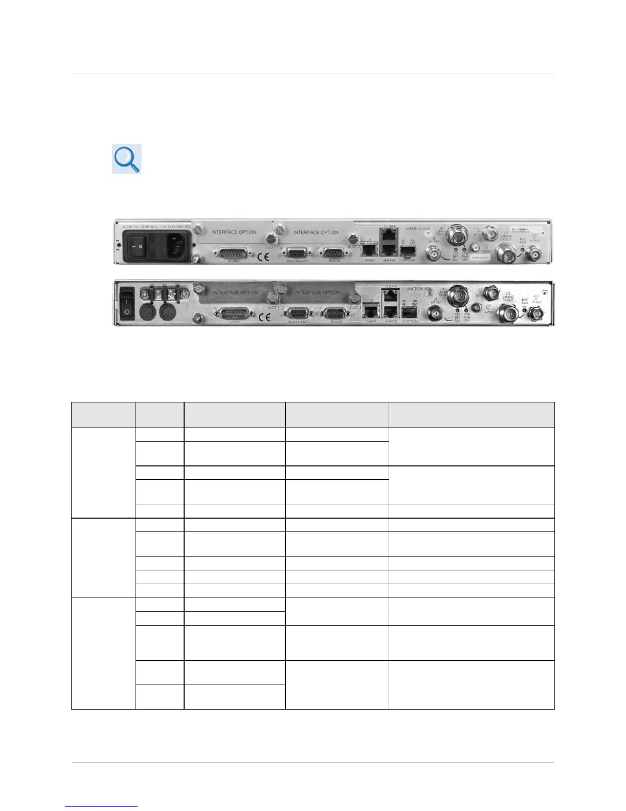
The rear panel connectors (Figure 3-3) provide all necessary external connections between the
unit and other equipment.
• For full information about the optional PIICs (Plug-In Interface Cards) and
their traffic data interface connectors, see Appendix C. PIIC OPTIONS.
• For full information about the optional High-Speed Packet Processor and its
management and traffic data interface connectors, see Appendix F.
OPTIONAL HIGH-SPEED PACKET PROCESSOR.
(TOP) Standard AC Unit
(BOTTOM) Optional 48V DC Unit (FUTURE)
Figure 3-3. CDM-760 Cabling Connections
Table 3-1. CDM-760 Rear Panel Connectors
Group Name
Ref Des Name Connector Type Function
IF
Connector
Group
(3.2.1)
IF Input
J11 IF RX IN
BNC female
IF Output
J13 IF TX OUT
BNC female
Utility
Connector
Group
(3.2.2)
Form C Alarms (relay closures)
J2 REDUNDANCY 9-pin Type ‘D’ female
Connection to External 1:1
Serial Remote Interface (EIA-485/232)
External Reference Input / Output
Terrestrial
Data
Connector
Group
(3.2.3)
RJ-45 female
10/100/1000 BaseT Gigabit Ethernet
traffic
J7 OPTICAL
SFP (Small Form
Factor Pluggable)
Accepts optional hot-pluggable SFP
1000Base-SX 850mm Transceiver
N/A
INTERFACE OPTION
PIIC (Plug-In Interface
Card) slots
Accepts optional data interface
modules (e.g., G.703 E3/T3/STS-1,
OC-3 Single / Multi Mode. STM-1
Copper, etc.)
N/A
INTERFACE OPTION