Menu 21 Introduction Parameter x.00
Parameter
description format
Keypad and
display
CT Modbus
RTU
User
programming
CT Soft Menu 0
Advanced parameter
descriptions
164 Commander SK Advanced User Guide
www.controltechniques.com Issue Number: 2
This parameter is used in the calculation of motor speed and in applying the correct slip compensation. When auto is selected the number of motor
poles is automatically calculated from the rated frequency (Pr 21.06) and the rated load rpm (Pr 21.08).
The number of poles = 120 x rated frequency / rpm rounded to the nearest even number.
This parameter contains the stator resistance of the machine for open loop vector mode operation.
If the drive cannot achieve the necessary current levels to measure the stator resistance during an auto-tune (e.g. there is no motor connected to the
drive) an rS trip will occur and the value in Pr 21.12 remains unchanged. If the necessary current levels can be achieved but the calculated resistance
exceeds the maximum allowable value for that particular drive size, an rS trip will occur and Pr 21.12 will contain the maximum allowable value.
Due to various effects in the drive inverter a voltage offset must be produced before any current flows. To obtain good performance at low frequencies
where the machine terminal voltage is small this offset must be taken into account. The value shown in Pr
21.13
is this offset given in line to line rms volts.
It is not possible for the user to measure this voltage easily, and so the automatic measurement procedure should be used (see Pr
5.14
on page 62).
With reference to the following diagram, the transient inductance is defined as
σL
s
= L
1
+ (L
2
.L
m
/ (L
2
+ L
m
))
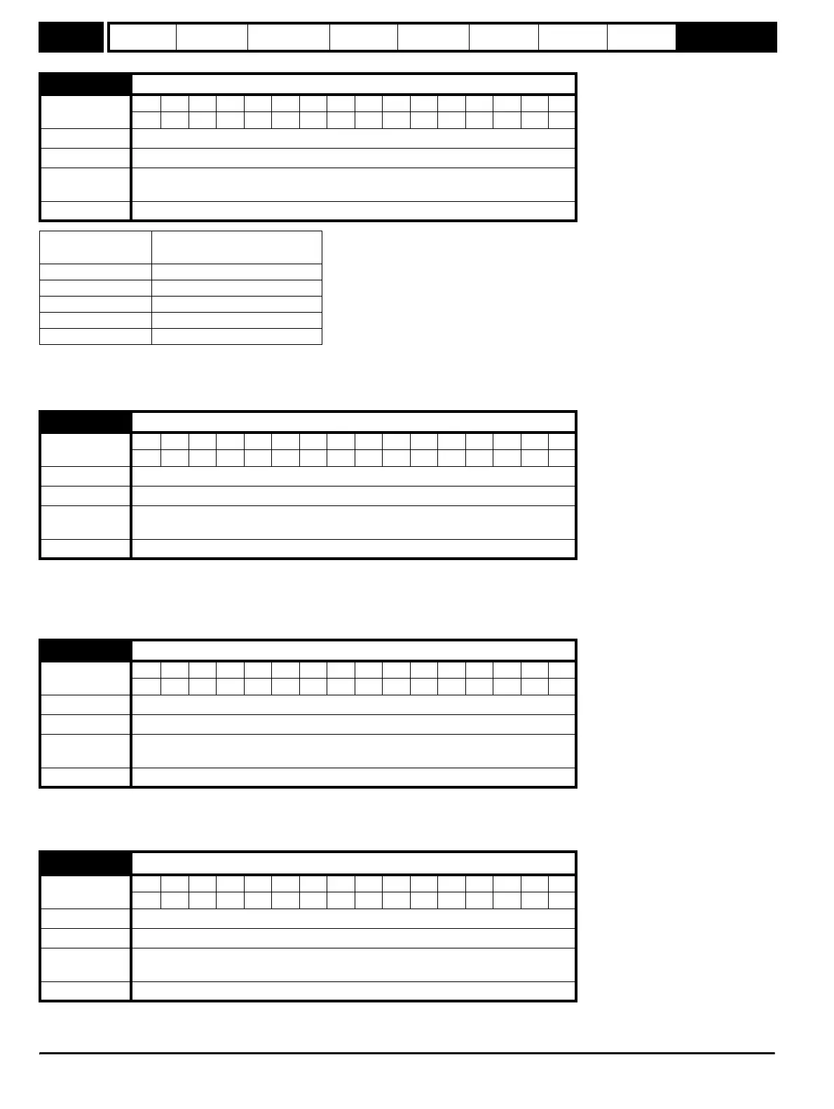
21.11 Motor 2 number of motor poles
Coding
Bit SP FI DE Txt VM DP ND RA NC NV PT US RW BU PS
1111
Range 0 (Auto), 1 (2P), 2 (4P), 3 (6P), 4 (8P)
Default 0 (Auto)
First motor
parameter
Pr 5.11
Update rate Background
Poles by text
(value on display)
Pole pairs
(value through serial comms)
Auto 0
2P 1
4P 2
6P 3
8P 4
21.12 Motor 2 stator resistance
Coding
Bit SP FI DE Txt VM DP ND RA NC NV PT US RW BU PS
31 111
Range 0.000 to 30.000
Ω
Default 3.0
First motor
parameter
Pr 5.17
Update rate Background
21.13 Motor 2 voltage offset
Coding
Bit SP FI DE Txt VM DP ND RA NC NV PT US RW BU PS
11 111
Range 0.0 to 25.0 V
Default 0.0
First motor
parameter
Pr 5.23
Update rate Background
21.14
Motor 2 transient inductance (
σL
s
)
Coding
Bit SP FI DE Txt VM DP ND RA NC NV PT US RW BU PS
21 11
Range 0.000 to 320.00 mH
Default 0.000
First motor
parameter
Pr 5.24
Update rate Background