Introduction Parameter x.00
Parameter
description format
Keypad and
display
CT Modbus
RTU
User
programming
CT Soft Menu 0
Advanced parameter
descriptions
Menu 21
Commander SK Advanced User Guide 165
Issue Number: 2 www.controltechniques.com
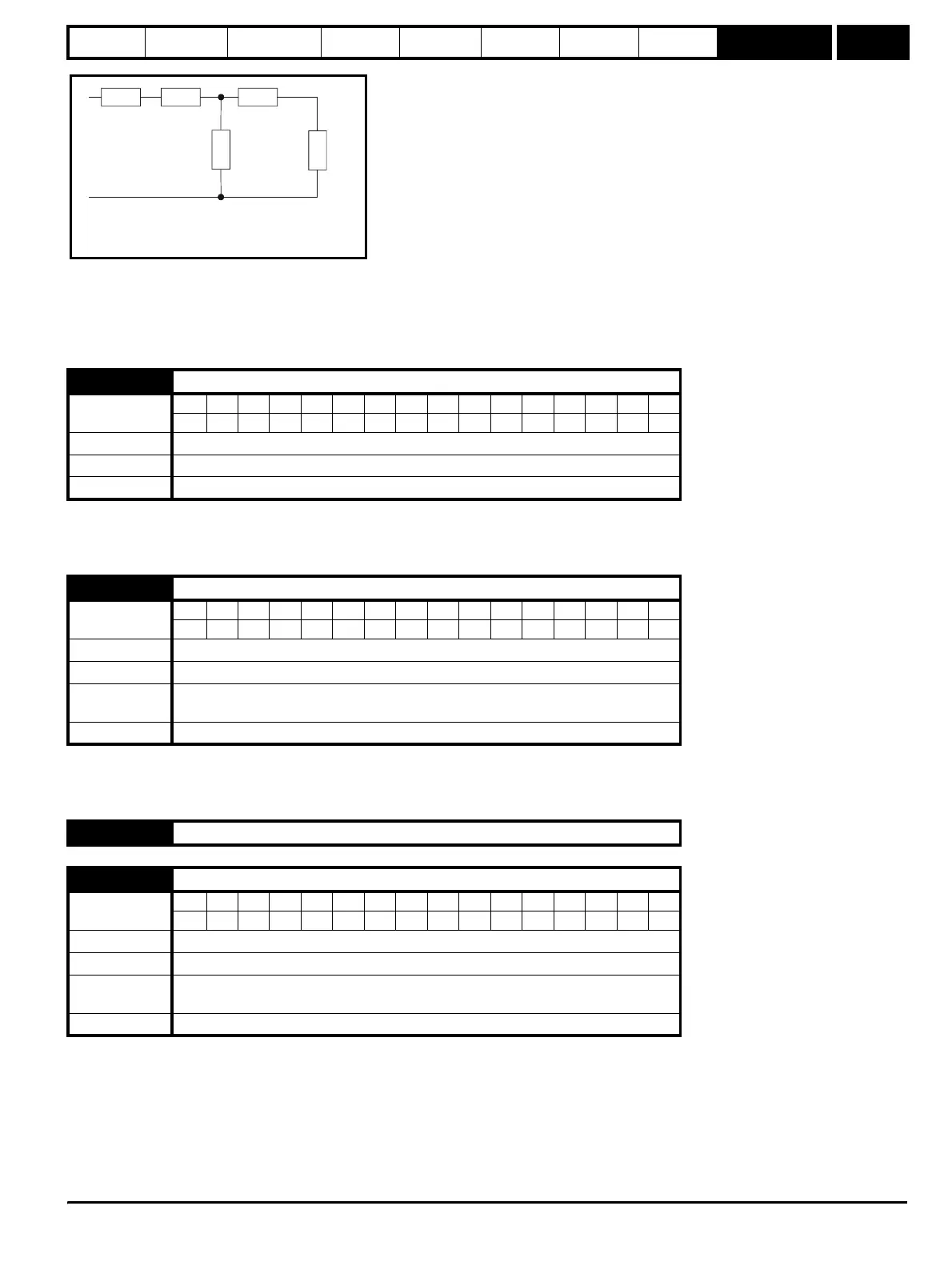
Based on the parameters normally used for the motor equivalent circuit for transient analysis, i.e. L
s
= L
1
+ L
m
, L
r
= L
2
+ L
m
, the transient inductance
is given by:
σL
s
= L
s
- (L
m
2
/ L
r
)
The transient inductance is used as an intermediate variable to calculate the power factor.
When this parameter is set to a 1, it signifies that motor map 2 is active.
This parameter can be programmed to a digital output to give a signal to an external circuit to close a second motor contactor when motor map 2
becomes active.
Pr 21.16 works in conjunction with Pr 4.16 and Pr 4.25. The motor protection modes set-up by Pr 4.16 and Pr 4.25 for motor 1 will be used for motor
2 but the thermal time constant for motor 2 will be defined in Pr 21.16.
See Pr 4.16 on page 51 and Pr 4.25 on page 54 for further details.
This parameter defines the current limit as a percentage of the rated active current. When the motor rated current is set lower than the drive rated
current, the maximum value of this parameter increases to allow larger overloads.
Therefore, by setting the motor rated current to a lower value than the drive rated current, it is possible to have a current limit greater than 165%. An
absolute maximum current limit of 999.9% is applied.
In frequency control mode (Pr 4.11 = 0), the drive output frequency is modified if necessary to keep the active current within the current limits as
shown in the following diagram:
21.15 Motor 2 active
Coding
Bit SP FI DE Txt VM DP ND RA NC NV PT US RW BU PS
1111
Range 0 or 1
Default 0
Update rate Background
21.16 Motor 2 thermal time constant
Coding
Bit SP FI DE Txt VM DP ND RA NC NV PT US RW BU PS
111
Range 0 to 250 s
Default 89
First motor
parameter
Pr 4.15
Update rate Background
21.17 to 21.28 Unused parameters
21.29 Motor 2 symmetrical current limit
Coding
Bit SP FI DE Txt VM DP ND RA NC NV PT US RW BU PS
11 1 111
Range 0 to MOTOR1_CURRENT_LIMIT_MAX %
Default 165.0
First motor
parameter
Pr 4.07
Update rate Background
R
1
jwL
1
jwL
2
R
2
/sjwL
m
Steady state per phase equivalent circuit
of an induction motor