Introduction Parameter x.00
Parameter
description format
Keypad and
display
CT Modbus
RTU
User
programming
CT Soft Menu 0
Advanced parameter
descriptions
Menu 5
Commander SK Advanced User Guide 61
Issue Number: 2 www.controltechniques.com
The following parameters are used in the vector control algorithm.
All these parameters can be set by the user except the transient inductance. The autotune test can be used to overwrite the user or default settings
as described below. Accurate values of stator resistance and voltage offset are required even for moderate performance in vector mode (an accurate
value of power factor is less critical).
1 Stationary test
The stationary test measures the stator resistance (Pr 5.17) and voltage offset (Pr 5.23). The power factor (Pr 5.10) is not affected.
2 Rotating test
A stationary test is performed to measure stator resistance (Pr 5.17), voltage offset (Pr 5.23) and transient inductance (Pr 5.24). The transient
inductance is not used directly by the drive, but is an intermediate value in determining the power factor after the rotating test. This is followed by a
rotating test in which the motor is accelerated with the currently selected ramps to
2
/
3
of rated speed and held at this speed for several seconds. Once
the test is complete the power factor (Pr 5.10) is updated and the motor coasts to a stop.
The motor should be unloaded for this test to produce correct results.
The autotune tests may be aborted by removing the run command or if a trip occurs. During the auto-tune tests the following trips can occur in
addition to the other drive trips.
The rS trip is produced if the drive cannot achieve the necessary current levels to measure the stator resistance during the test (i.e. there is no motor
connected to the drive), or if the necessary current level can be achieved, but the calculated resistance exceeds the maximum values for the
particular drive size. The maximum measurable value can be calculated from the following formula.
Rs
max
= DC_VOLTAGE_MAX / (Drive rated current x √2 x 2)
It is important to make sure that the motor wiring configuration is correct (i.e. Star/Delta) before performing an autotune.
If any changes are made to the drive's motor map parameter, system wiring, motor wiring configuration or motor size or type, the drive must be re-
autotuned to the motor. Not performing another auto-tune will result in poor motor performance, OI.AC or It.AC trips.
0: Variable torque select disabled
1: Variable torque select enabled
Setting this bit to a 1 enables variable torque mode which is intended for applications where power loss should be kept to a minimum under low load
conditions. The V/f ratio is modified with load as follows:
If |active current| < 0.7 x rated active current
V/f ratio = Normal V/f ratio x (0.5 + (active current / (2 x 0.7 x rated active current)))
Else, if |active current| ≥ 0.7 x rated active current
V/f ratio = Normal V/f ratio
Although the rated frequency varies, the value shown as Pr 5.06 does not vary from that set by the user.
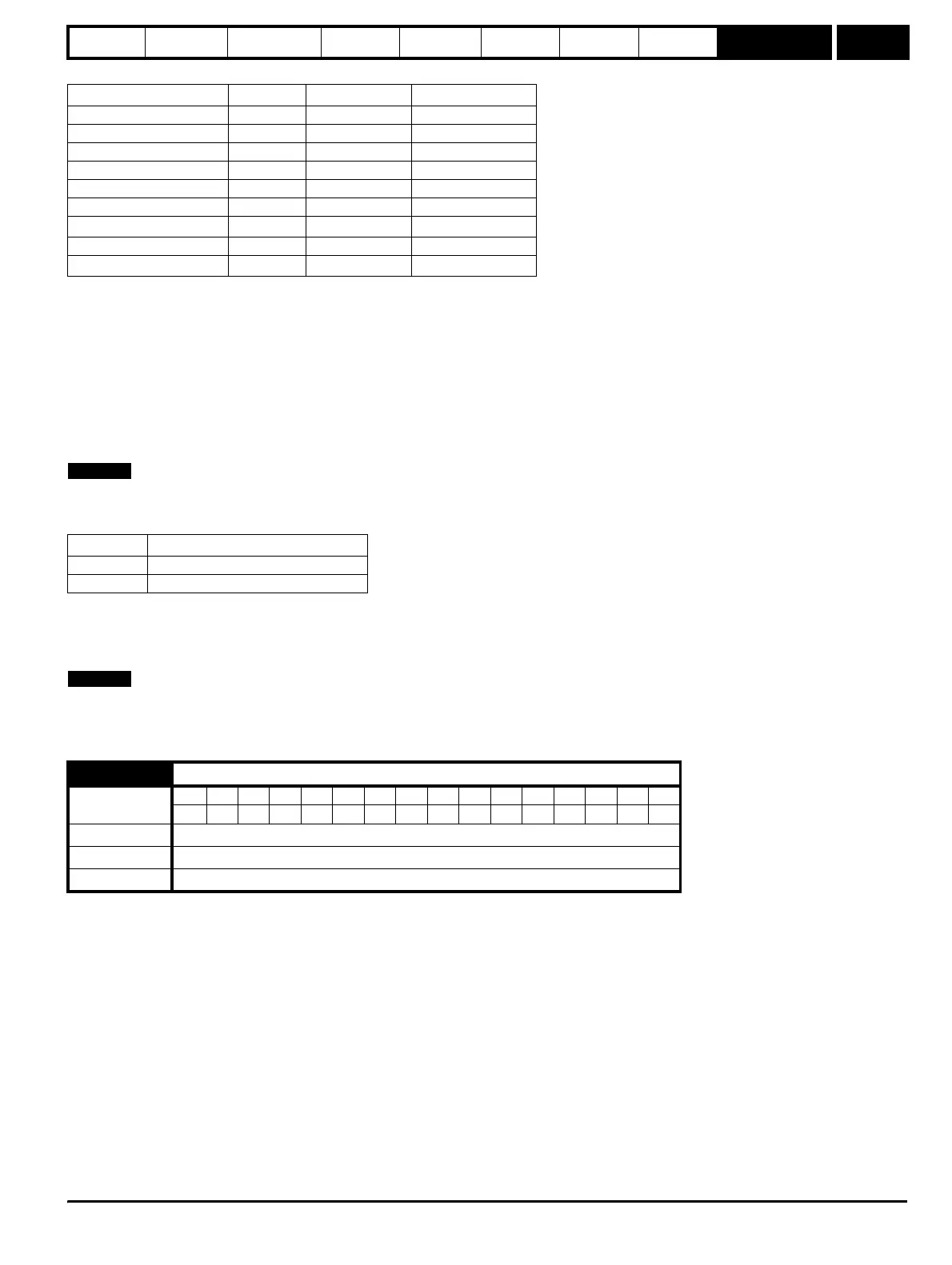
Parameter Basic algorithm Slip compensation
Rated frequency 5.06 99
Rated current 5.07 99
Rated load rpm 5.08 9
Rated voltage 5.09 9
Power factor 5.10 9
No. of poles 5.11 9
Stator resistance (R
s
)
5.17 9
Voltage offset 5.23 9
Transient inductance (σL
s
)
5.24
Trip code Reason
tunE Auto-tune stopped before completion
rS Stator resistance too high
5.13 Variable torque select
Coding
Bit SP FI DE Txt VM DP ND RA NC NV PT US RW BU PS
111
Range 0 or 1
Default 0
Update rate Background
NOTE
NOTE