Menu 5 Introduction Parameter x.00
Parameter
description format
Keypad and
display
CT Modbus
RTU
User
programming
CT Soft Menu 0
Advanced parameter
descriptions
64 Commander SK Advanced User Guide
www.controltechniques.com Issue Number: 2
Due to various effects in the drive inverter a voltage offset must be produced before any current flows. To obtain good performance at low frequencies
where the machine terminal voltage is small this offset must be taken into account. The value shown in Pr 5.23 is this offset given in line to line rms
volts. It is not possible for the user to measure this voltage easily, and so the automatic measurement procedure should be used (see Pr 5.14 on page
62).
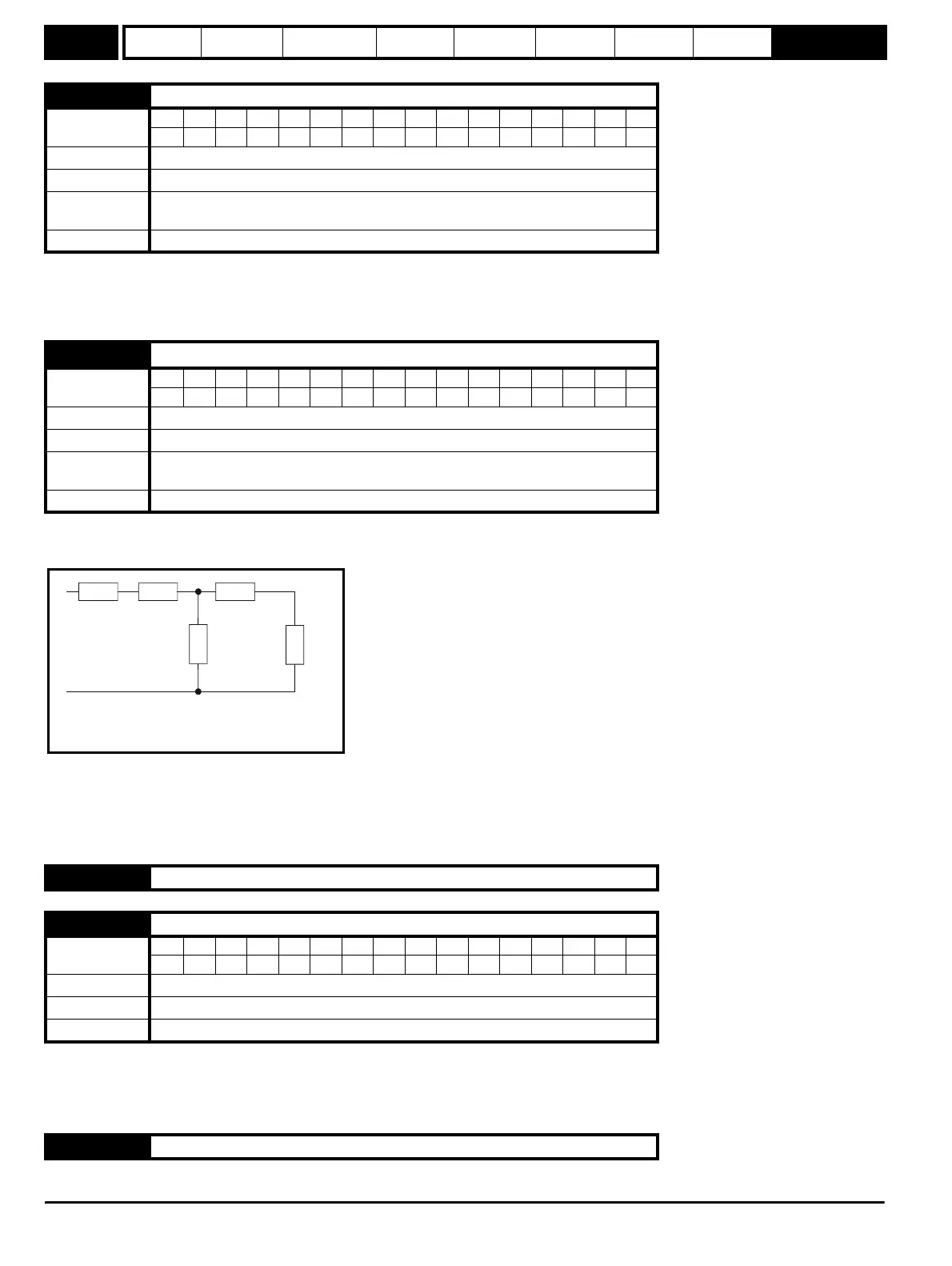
With reference to the diagram below, the transient inductance is defined as
σL
s
= L
1
+ (L
2
.L
m
/ (L
2
+ L
m
))
Based on the parameters normally used for the motor equivalent circuit for transient analysis, i.e. L
s
= L
1
+ L
m
, L
r
= L
2
+ L
m
, the transient inductance
is given by:
σL
s
= L
s
- (L
m
2
/ L
r
)
The transient inductance is used as an intermediate variable to calculate the power factor.
0: Slip compensation disabled
1: Slip compensation enabled
The level of slip compensation is set by the rated frequency and rated speed parameters. Slip compensation is only enabled when this parameter is
set to 1 and Pr 5.08 is set to a value other than zero or synchronous speed.
5.23 Voltage offset
Coding
Bit SP FI DE Txt VM DP ND RA NC NV PT US RW BU PS
11 111
Range 0.0 to 25.0 V
Default 0.0
Second motor
parameter
Pr 21.13
Update rate Background
5.24
Transient inductance (σL
s
)
Coding
Bit SP FI DE Txt VM DP ND RA NC NV PT US RW BU PS
21 11
Range 0.000 to 320.00 mH
Default 0.000
Second motor
parameter
Pr 21.14
Update rate Background
5.25 to 5.26 Unused parameters
5.27 Enable slip compensation
Coding
Bit SP FI DE Txt VM DP ND RA NC NV PT US RW BU PS
1111
Range 0 or 1
Default 1
Update rate Background
5.28 to 5.33 Unused parameters
R
1
jwL
1
jwL
2
R
2
/sjwL
m
Steady state per phase equivalent circuit
of an induction motor