Menu 4 Introduction Parameter x.00
Parameter
description format
Keypad and
display
CT Modbus
RTU
User
programming
CT Soft Menu 0
Advanced parameter
descriptions
50 Commander SK Advanced User Guide
www.controltechniques.com Issue Number: 2
If operating in torque control, due to small errors in current measurement at low frequencies, with zero torque reference and light loads, the drive may
allow the motor to rotate. The direction of rotation while in torque control is determined by the polarity of the torque reference. Therefore, at power-up
with zero torque reference and with the drive enabled, the motor may rotate in either direction. This is because any error in the current feedback
maybe a positive or negative value. If the error is positive, the motor will rotate in the forward direction and if the error is negative, the motor will rotate
in the reverse direction.
If it is necessary to guarantee the direction of rotation at power up while in torque control, a small positive or negative error must be present in Pr 4.08.
0: Torque mode disabled
1: Torque mode enabled
If this parameter is 0 normal frequency control is used.
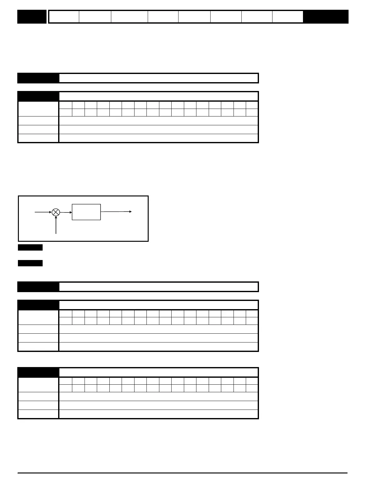
If this parameter is set to 1 the current demand is connected to the current PI controller giving closed loop torque/current demand as shown below.
The current error is passed through proportional and integral terms to give a frequency reference. In motoring conditions the frequency reference is
limited to the maximum frequency set up in menu 1, while for regeneration the frequency reference is allowed to go up to the maximum programmed
in menu 1 + 20% to allow for current control close to maximum speed.
This parameter can be changed from 0 to 1 when the drive is still running, the drive does not have to be disabled or stopped etc.
When torque control is enabled, slip compensation is automatically disabled to prevent overspeed trips (O.SPd)
See Pr 4.14 for details.
These parameters control the proportional and integral gains of the current controller. As already mentioned the current controller either provides
current limits or closed loop torque control by modifying the drive output frequency. The control loop is also used in its torque mode during mains loss,
or when the controlled mode standard ramp is active and the drive is decelerating, to regulate the flow of current into the drive. Although the default
settings have been chosen to give suitable gains for less demanding applications it may be necessary for the user to adjust the performance of the
controller. The following is a guide to setting the gains for different applications.
Current limit operation
The current limits will normally operate with an integral term only, particularly below the point where field weakening begins. The proportional term is
4.09 to 4.10 Unused parameters
4.11 Torque mode selector
Coding
Bit SP FI DE Txt VM DP ND RA NC NV PT US RW BU PS
111
Range 0 or 1
Default 0
Update rate Background
4.12 Unused parameter
4.13 Current controller Kp gain
Coding
Bit SP FI DE Txt VM DP ND RA NC NV PT US RW BU PS
111
Range 0 to 250
Default 250
Update rate Background
4.14 Current controller Ki gain
Coding
Bit SP FI DE Txt VM DP ND RA NC NV PT US RW BU PS
111
Range 0 to 250
Default 40
Update rate Background
P Pr
4.13
I Pr
4.14
urrent
demand
Active
rr
nt
Frequency
reference
+
-
NOTE
NOTE