Menu 11 Introduction Parameter x.00
Parameter
description format
Keypad and
display
CT Modbus
RTU
User
programming
CT Soft Menu 0
Advanced parameter
descriptions
120 Commander SK Advanced User Guide
www.controltechniques.com Issue Number: 2
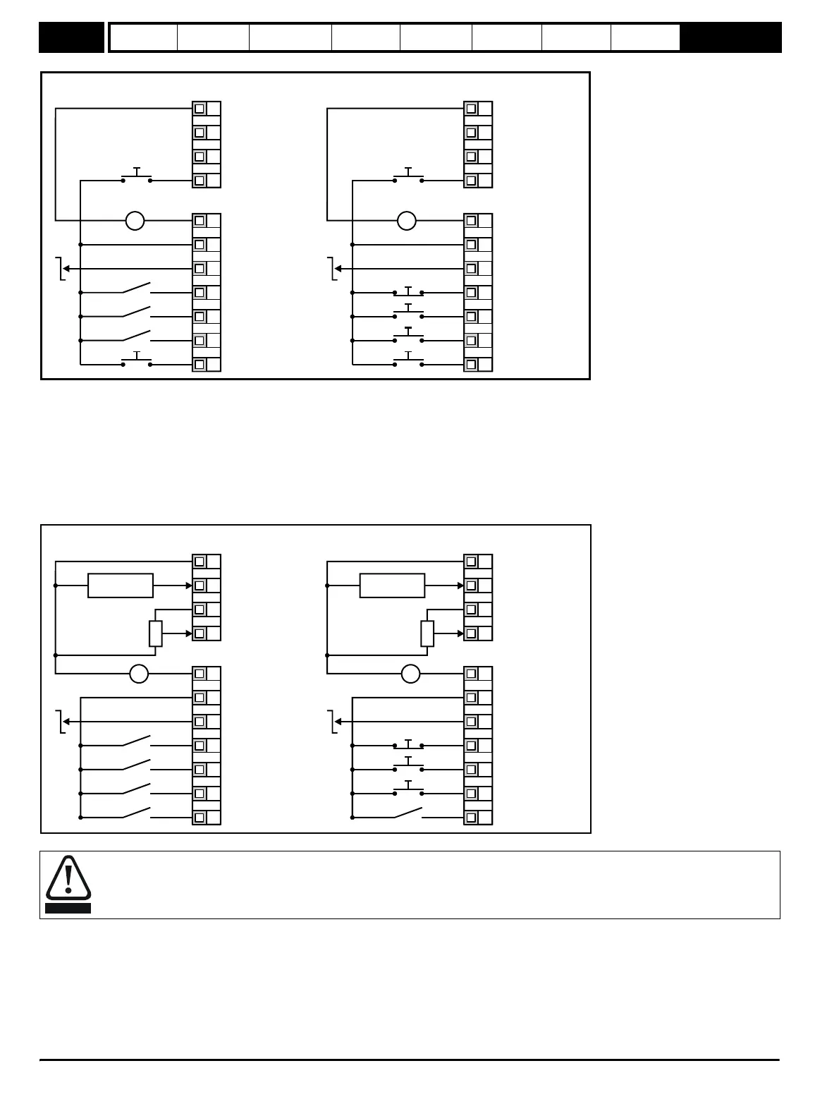
Figure 9-31 Pr 11.27 = E.Pot
When Pr 11.27 is set to E.Pot, the following parameters are made available for adjustment:
•Pr 9.23: Motorised pot up/down rate (s/100%)
•Pr 9.22: Motorised pot bipolar select (0 = unipolar, 1 = bipolar)
•Pr 9.21: Motorised pot mode:
0 = zero at power-up
1 = last value at power-up
2 = zero at power-up and only change when drive is running
3 = last value at power-up and only change when drive is running
Figure 9-32 Pr 11.27 = tor
When torque mode is selected and the drive is connected to an unloaded motor, the motor speed may increase rapidly to the maximum
speed (Pr 02 +20%)
0V
+10V reference output
+24V output
Drive Enable/Reset
Run Forward
Run Reverse
V
_
+
+24V
0V
EUR U
A
Analog output
(motor speed)
Digital output
(zero speed)
Down
Up
Not used
0V
+10V reference outpu
+24V output
Not Stop
Run
Jog
V
_
+
+24V
0V
Analog output
(motor speed)
Digital output
(zero speed)
Down
Up
Not used
T1
T2
T3
T4
B1
B2
B3
B4
B5
B6
B7
T1
T2
T3
T4
B1
B2
B3
B4
B5
B6
B7
0V
Remote current speed
reference input (A1)
+10V reference output
Torque reference
input (A2)
+24V output
Drive Enable/Reset
Run Forward
Run Reverse
Torque mode
l
t
Remote speed
reference input
V
_
+
10k
(2kmin)
+24V
0V
EUR U
A
Analog output
(motor speed)
Digital output
(zero speed)
0V
Remote current speed
reference input (A1)
+10V reference outpu
Torque reference
input (A2)
+24V output
Not Stop
Run
Jog
Torque mode
l
t
Remote speed
reference input
V
_
+
10k
(2kmin)
+24V
0V
Analog output
(motor speed)
Digital output
(zero speed)
T1
T2
T3
T4
B1
B2
B3
B4
B5
B6
B7
T1
T2
T3
T4
B1
B2
B3
B4
B5
B6
B7
WARNING