Introduction Parameter x.00
Parameter
description format
Keypad and
display
CT Modbus
RTU
User
programming
CT Soft Menu 0
Advanced parameter
descriptions
Menu 6
Commander SK Advanced User Guide 71
Issue Number: 2 www.controltechniques.com
When the drive is enabled with this bit at 0, the output frequency starts at zero and ramps to the required reference. When the drive is enabled and
this parameter has a non-zero value, the drive performs a start-up test to determine the motor speed and then sets the initial output frequency to the
synchronous frequency of the motor. The test is not carried out, and the motor frequency starts at zero, if the run command is given when the drive is
in the stop state, or when the drive is first enabled after power up with UR I voltage mode, or when the run command is given in UR S voltage mode.
For the test to operate correctly it is important that the stator resistance (Pr 5.17, Pr 21.12) is set up correctly. This applies even if fixed boost (Fd) or
square law (SrE) voltage mode is being used. The test uses the rated magnetising current of the motor during the test, therefore the rated current
(Pr 5.07, Pr 21.07 and Pr 5.10, Pr 21.10) and power factor should be set to values close to those of the motor, although these parameters are not as
critical as the stator resistance.
Stationary lightly loaded motors with low inertia may move slightly during the test. The direction of the movement is undefined. Restrictions may be
placed on the direction of this movement and on the frequencies detected by the drive as in the above table.
0: Low DC bus operation disabled
1: Low DC bus operation enabled
On the 400V product setting this bit will enable the drive to run off 240Vac input. The current limit will automatically be reduced therefore only allowing
the drive to operate at a lower power rating.
6.08 Unused parameter
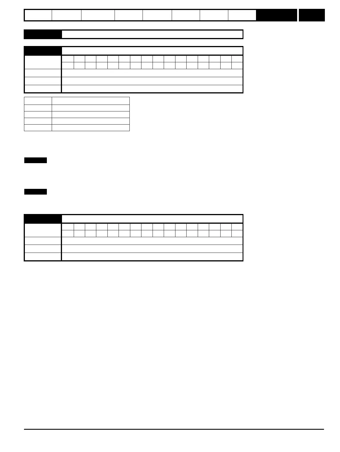
6.09 Catch a spinning motor
Coding
Bit SP FI DE Txt VM DP ND RA NC NV PT US RW BU PS
111
Range 0 to 3
Default 0
Update rate Background
Pr 6.09 Function
0 Disabled
1 Detect all frequencies
2 Detect positive frequencies only
3 Detect negative frequencies only
6.10 Low DC bus operation
Coding
Bit SP FI DE Txt VM DP ND RA NC NV PT US RW BU PS
111
Range 0 or 1
Default 0
Update rate Background
NOTE
NOTE