Introduction Parameter x.00
Parameter
description format
Keypad and
display
CT Modbus RTU
User
programming
CT Soft Menu 0
Advanced parameter
descriptions
Commander SK Advanced User Guide 7
Issue Number: 2 www.controltechniques.com
3.2.2 Parameter types
There are two fundamental types of parameters in the drive, read only (RO) and read/write (RW). The read only parameters cannot be changed by
the user and are there to give the user useful information about the state of the drive. Read/write parameters are for the user to set up the way in
which the drive operates.
Parameters can be further broken down into Bit parameters and Non-bit parameters. Bit parameters are two state only (0 or 1) and if RW are used as
switches or two state input variables to the drive logic, or if RO indicate various drive conditions which are either true (1) or false (0). Non-bit
parameters have more than two values the range of each being given in the following descriptions.
In the basic parameter set, some parameters are represented as strings rather than numeric values which give a more informative indication of the
parameter setting.
Since the parameters in the basic parameter set are copies of extended parameters, the strings are indicated as well as the numeric value. Setting-up
via the serial interface requires numeric data.
Most parameters when being adjusted take immediate effect, but destination and source parameters do not. Using these parameter values while they
are being adjusted could cause a malfunction in the operation of the drive if an intermediary value were taken during the adjustment. For the new
value of one of these parameters to take effect a 'Drive Reset' must be carried out (see section 3.2.4 Drive reset ).
Any changes made to parameters over the serial interface are not stored in the drives EEPROM until a manual store is initiated.
3.2.3 32 bit parameters
32 bit parameters cannot be displayed on the LED display. Source and destination parameters cannot be set to 32 bit parameters.
3.2.4 Drive reset
A drive reset is required for a number of reasons:
• To reset the drive from a tripped state
• To initiate loading of default parameters
• To implement a change in the value of certain parameters
• To initiate the saving of parameters in EEPROM
The later two of these can be done while the drive is running.
The drive can be reset in one of four ways:
1. The drive will be reset with a 0 to 1 transition of the enable input when the drive is tripped, such that a dedicated reset terminal is not required.
2. The drive will be reset when a 0 to 1 transition of the Drive Reset parameter Pr 10.33. This parameter is provided for control by a programmable
digital input such that a terminal can be used to reset the drive.
3. The Stop/Reset key. If the drive is not in keypad mode and the 'always stop' parameter is not set, then the key has a drive reset function only. In
keypad mode or if the 'always stop' parameter is set, a drive reset can be done while the drive is running by holding the Run key while the Stop/
Reset key is activated. When the drive is not running the Stop/Reset key will always reset the drive.
4. By the serial interface. This drive reset is triggered by a value of 100 being written to the User trip parameter Pr 10.38.
3.2.5 Storing drive parameters
When the keypad is used to edit a parameter, the parameter is stored when the mode key is pressed after adjustment has been made.
When using the serial interface, parameters are stored by setting Pr x.00 to a value of 1000 and performing a 'Drive reset'. Because a 'Drive reset'
causes the values of certain parameters to be implemented, storing parameters has the effect of implementing all new values as the store takes
place.
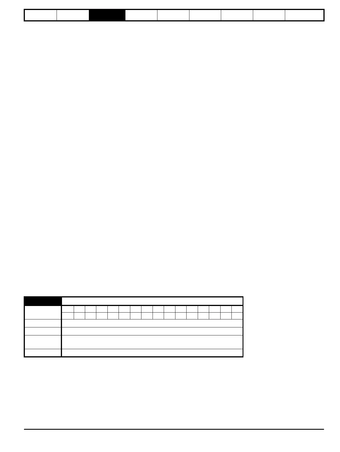
3.3 Key to parameter codes
In the following sections descriptions are given for the advanced parameter set. With each parameter the following information block is given.
The top row gives the menu:parameter number and the parameter name. The other rows give the following information.
5.11 Number of motor poles
Coding
Bit SP FI DE Txt VM DP ND RA NC NV PT US RW BU PS
1 111
Range 0 (Auto), 1 (2P), 2 (4P), 3 (6P), 4 (8P)
Default 0 (Auto)
Second motor
parameter
Pr 21.11
Update rate Background