Menu 12 Introduction Parameter x.00
Parameter
description format
Keypad and
display
CT Modbus
RTU
User
programming
CT Soft Menu 0
Advanced parameter
descriptions
128 Commander SK Advanced User Guide
www.controltechniques.com Issue Number: 2
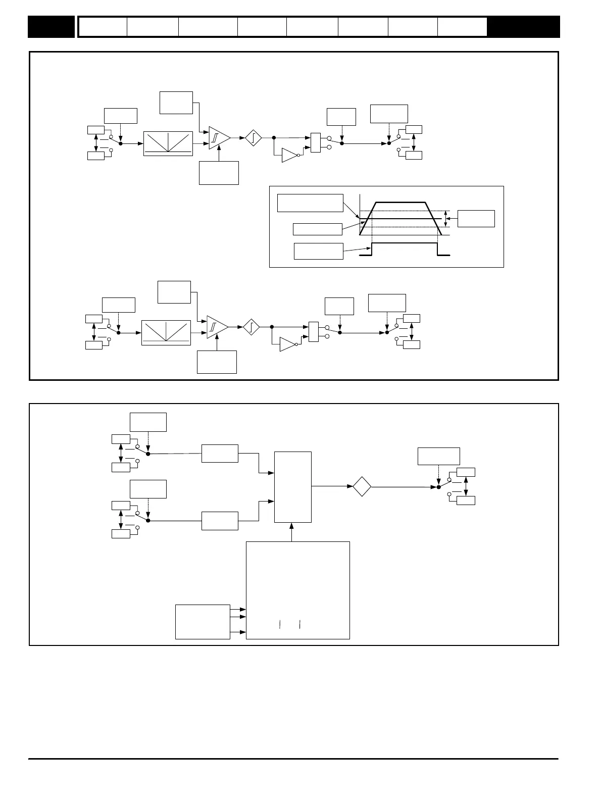
Figure 9-36 Menu 12A logic diagram
Figure 9-37 Menu 12B logic diagram
Threshold
exceeded 1
12.01
Threshold detector 1
21.51
0.01
Source 1
12.03
0
1
Invert 1
12.06
Threshold
level 1
12.04
Hysteresis 1
12.05
21.51
1.01
Destination 1
12.07
Threshold
exceeded 2
12.02
Threshold detector 2
21.51
0.01
Source 2
12.23
0
1
Invert 2
12.26
Threshold
level 2
12.24
Hysteresis 2
12.25
21.51
1.01
Destination 2
12.27
MENU 12
Threshold Detectors
12.04/12.24 (% of maximum
of source)
Hysteresis
12.05/12.25
Threshold exceeded
12.01/12.02
Threshold source
21.51
0.01
Source 2
12.09
21.51
0.01
Source 1
12.08
Scaling
12.13
Scaling
12.14
21.51
1.01
Destination
12.11
Output
12.12
%
Variable selector
control
12.15
Input 1
Input 2
Variable selector modes 12.10
0 - 12.12 = Input 1
1 - 12.12 = Input 2
2 - 12.12 = Input 1 + Input 2
3 - 12.12 = Input 1 - Input 2
4 - 12.12 = (Input 1 x Input 2) / 100
5 - 12.12 = (Input 1 x 100) / Input 2
6 - 12.12 = Input 1 / (12.15s + 1)
7 - 12.12 = Input 1 via Ramp
8 - 12.12 = Input 1
9 - 12.12 = Input 1
12.15
MENU 12B
Variable Selector 1