Introduction Parameter x.00
Parameter
description format
Keypad and
display
CT Modbus
RTU
User
programming
CT Soft Menu 0
Advanced parameter
descriptions
Menu 21
Commander SK Advanced User Guide 163
Issue Number: 2 www.controltechniques.com
modes to operate correctly the stator resistance (Pr 21.12), motor rated power factor (Pr 21.10) and voltage offset (Pr 21.13) are all required to be set-
up accurately.
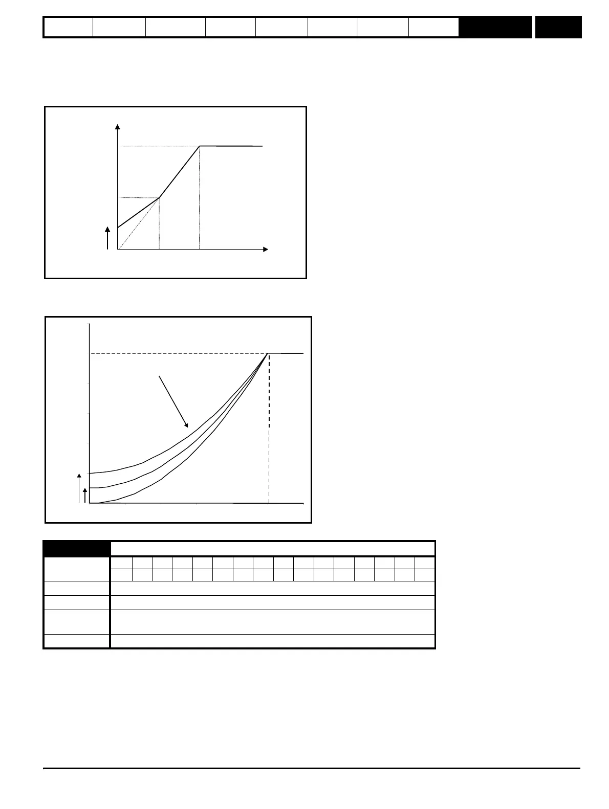
Fixed boost mode: Fd
A linear characteristic is used from 0Hz to rated frequency, and then constant voltage above rated frequency. Low frequency voltage boost as defined
by Pr 5.15 is applied as shown below.
Square law mode: SrE
A square law characteristic is used from 0Hz to rated frequency, and then constant voltage above rated frequency. Low frequency voltage boost
raises the start point of the square law characteristic as shown below.
The power factor is the true power factor of the motor, i.e. the angle between the motor voltage and current. The power factor is used in conjunction
with the motor rated current (Pr 21.07) to calculate the rated active current and magnetising current of the motor. The rated active current is used
extensively to control the drive, and the magnetising current is used in vector mode Rs compensation. It is important that this parameter is set up
correctly.
21.10 Motor 2 motor rated power factor
Coding
Bit SP FI DE Txt VM DP ND RA NC NV PT US RW BU PS
2 111
Range 0.00 to 1.00
Default 0.85
First motor
parameter
Pr 5.10
Update rate Background
Voltage
boost Pr
5.15
Output
voltage
Pr
21.09
Pr / 2
21.09
Pr / 2
21.06
Pr
21.06
Output
frequenc
utput voltage characteristic
Pr
21.09
Pr
5.15
Pr
21.
Pr + [(freq/Pr ) x (Pr - Pr )]
5.15 21.06 21.09 5.15
2