Introduction Parameter x.00
Parameter
description format
Keypad and
display
CT Modbus
RTU
User
programming
CT Soft Menu 0
Advanced parameter
descriptions
Menu 10
Commander SK Advanced User Guide 107
Issue Number: 2 www.controltechniques.com
This parameter is set if the drive output current is larger than 105% of rated current (Pr 5.07) and the overload accumulator is greater than 75% to
warn that if the motor current is not reduced the drive will trip on an Ixt overload. (If the rated current [Pr 5.07] is set to a level above the rated drive
current [Pr 11.32] the overload alarm is given when the current is higher than 100% of rated current.)
This flag is set if the IGBT junction temperature calculated from the drive thermal model is above 135
°C, or if the heat sink temperature has made the
switching frequency decrease.
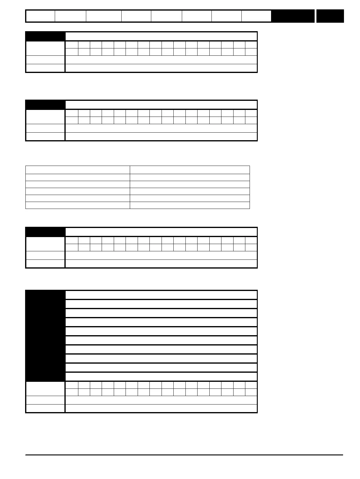
The following table indicates how the switching frequency is controlled:
The switching frequency and drive thermal model are updated once per second. Whenever the drive has reduced the switching frequency this alarm
is set.
This flag is set if any of the other drive alarms are active, i.e.
Drive temperature alarm, Overload alarm or Dynamic brake alarm.
Pr 10.19 = Pr 10.18 or Pr 10.17 or Pr 10.12
Contains the last 10 drive trips. Pr 10.20 is the most recent trip and Pr 10.29 the oldest. When a new trip occurs all the parameters move down one,
the current trip is put in 10.20 and the oldest trip is lost off the bottom of the log. Possible trips for Commander SK are shown in Table 9-13 on
page 108. All trips are stored including HF trips which are numbered from 20 to 30. (HF trips below numbered from 1 to 19 are not stored in the trip
log.) UU trips are not stored unless the drive is running when the trip occurs. Any trip can be initiated by the actions described or by writing the
relevant trip number to Pr 10.38. If any trips shown as user trips are initiated the trip string is “txxx”, where xxx is the trip number.
10.17 Overload alarm
Coding
Bit SP FI DE Txt VM DP ND RA NC NV PT US RW BU PS
1111
Range 0 or 1
Update rate Background
10.18 Drive temperature alarm
Coding
Bit SP FI DE Txt VM DP ND RA NC NV PT US RW BU PS
1111
Range 0 or 1
Update rate Background
Drive condition Action
Heat sink > 95
°C Trip drive
Heat sink > 92
°C Reduce switching frequency to 3kHz
Heat sink > 88
°C Reduce switching frequency to 6kHz
Heat sink > 85
°C Reduce switching frequency to 12kHz
IGBT temp > 135
°C Reduce switching frequency, if it is minimum trip drive
10.19 General drive alarm
Coding
Bit SP FI DE Txt VM DP ND RA NC NV PT US RW BU PS
1111
Range 0 or 1
Update rate Background
10.20 Last trip
10.21 Trip 1
10.22 Trip 2
10.23 Trip 3
10.24 Trip 4
10.25 Trip 5
10.26 Trip 6
10.27 Trip 7
10.28 Trip 8
10.29 Trip 9
Coding
Bit SP FI DE Txt VM DP ND RA NC NV PT US RW BU PS
111111
Range 0 to 230
Update rate On drive trip