Menu 7 Introduction Parameter x.00
Parameter
description format
Keypad and
display
CT Modbus
RTU
User
programming
CT Soft Menu 0
Advanced parameter
descriptions
82 Commander SK Advanced User Guide
www.controltechniques.com Issue Number: 2
This parameter displays the level of the analog signal present at analog input 1.
In voltage mode, this is a unipolar voltage input where the input range is 0 to +10V.
In current mode, this is a unipolar current input having a maximum measurable input of 20mA. The drive can be programmed to convert the measured
current to any one of the defined ranges in Pr 7.06. The selected range is converted to 0 to 100.0%, the resolution being 10 bit for the 0 - 20mA range.
This parameter display's the level of the analog input 2.
This is a unipolar voltage input having a range of 0 to +10V which is converted to 0 - 100%, the resolution being 10 bits.
Analog input 2 can also be configured as a digital input in which case this parameter will indicate 0 or 100% depending on the state of the input.
This parameter displays the temperature currently being measured on the heat sink. If the level reaches 95
°C the drive will trip O.ht2 on the display.
This is used as part of the drive's thermal model, see Pr 10.18 on page 107 for further details.
Terminal T2 is a voltage/current reference input. The setting of this parameter configures the terminal for the required mode.
In modes 2 and 3, a current loop loss trip (cL1) will be generated if the current input falls below 3mA.
If 4-20 or 20-4 modes are selected and the drive trips on current loop loss (cL1), analog reference 2 cannot be selected if the current reference is less
than 3mA.
If 4-.20 or 20-.4 modes are selected, Pr 7.28 will switch from a 0 to 1 to indicate that the current reference is less than 3mA.
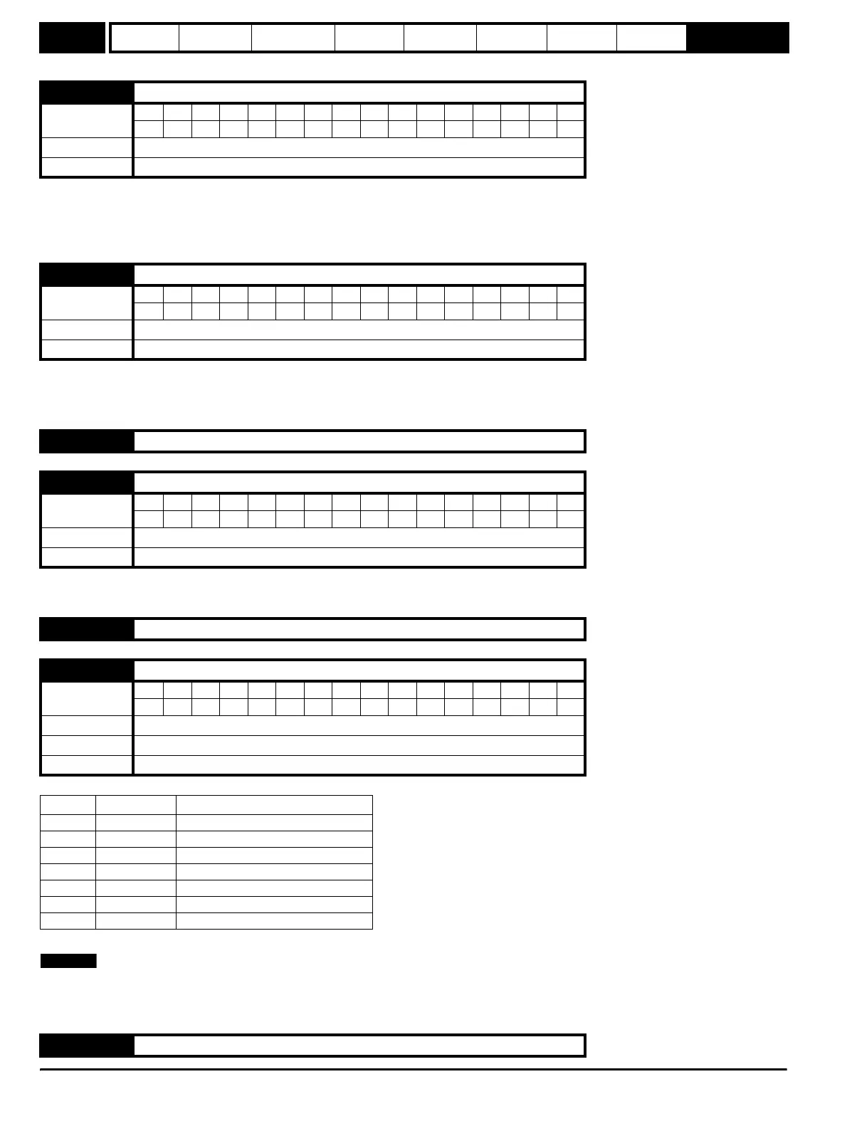
7.01 Analog input 1 monitor (terminal T2)
Coding
Bit SP FI DE Txt VM DP ND RA NC NV PT US RW BU PS
1111 1
Range 0.0 to 100.0 %
Update rate 5 ms
7.02 Analog input 2 monitor (terminal T4)
Coding
Bit SP FI DE Txt VM DP ND RA NC NV PT US RW BU PS
1111 1
Range 0.0 to 100.0 %
Update rate 5 ms
7.03 Unused parameter
7.04 Heatsink temperature
Coding
Bit SP FI DE Txt VM DP ND RA NC NV PT US RW BU PS
111
Range -128
°C to 127°C
Update rate Background
7.05 Unused parameter
7.06 Analog input 1 mode (terminal T2)
Coding
Bit SP FI DE Txt VM DP ND RA NC NV PT US RW BU PS
111
Range 0 to 6
Default 4
Update rate Background
Value Display Function
0 0-20 0 to 20mA
1 20-0 20 to 0mA
2 4-20 4 to 20mA with trip on loss
3 20-4 20 to 4mA with trip on loss
4 4-.20 4 to 20mA with no trip on loss
5 20-.4 20 to 4mA with no trip on loss
6 VoLt 0 to +10 volts
7.07 Unused parameter
NOTE