Menu 6 Introduction Parameter x.00
Parameter
description format
Keypad and
display
CT Modbus
RTU
User
programming
CT Soft Menu 0
Advanced parameter
descriptions
70 Commander SK Advanced User Guide
www.controltechniques.com Issue Number: 2
If normal or timed injection braking is selected, the drive will use ramp mode to stop on loss of the supply. If ramp stop followed by injection braking is
selected the drive will ramp to a stop and then attempt to apply DC injection. At this point, unless the mains has been restored the drive is likely to
initiate a UU trip.
2rd.th
The drive detects mains loss when the DC bus voltage falls below Vml
1
. The drive then enters a mode where a closed-loop controller attempts to hold
the DC bus level at Vml
2
. This causes the motor to decelerate at a rate that increases as the speed falls. If the mains is re-applied it will force the DC
bus voltage above the detection threshold Vml
1
and the drive will continue to operate normally. The output of the mains loss controller is a current
demand that is fed into the current control system and therefore the gain parameters Pr 4.13 and Pr 4.14 must be set up for optimum control. See
Pr 4.13 and Pr 4.14 on page 50 for set-up details.
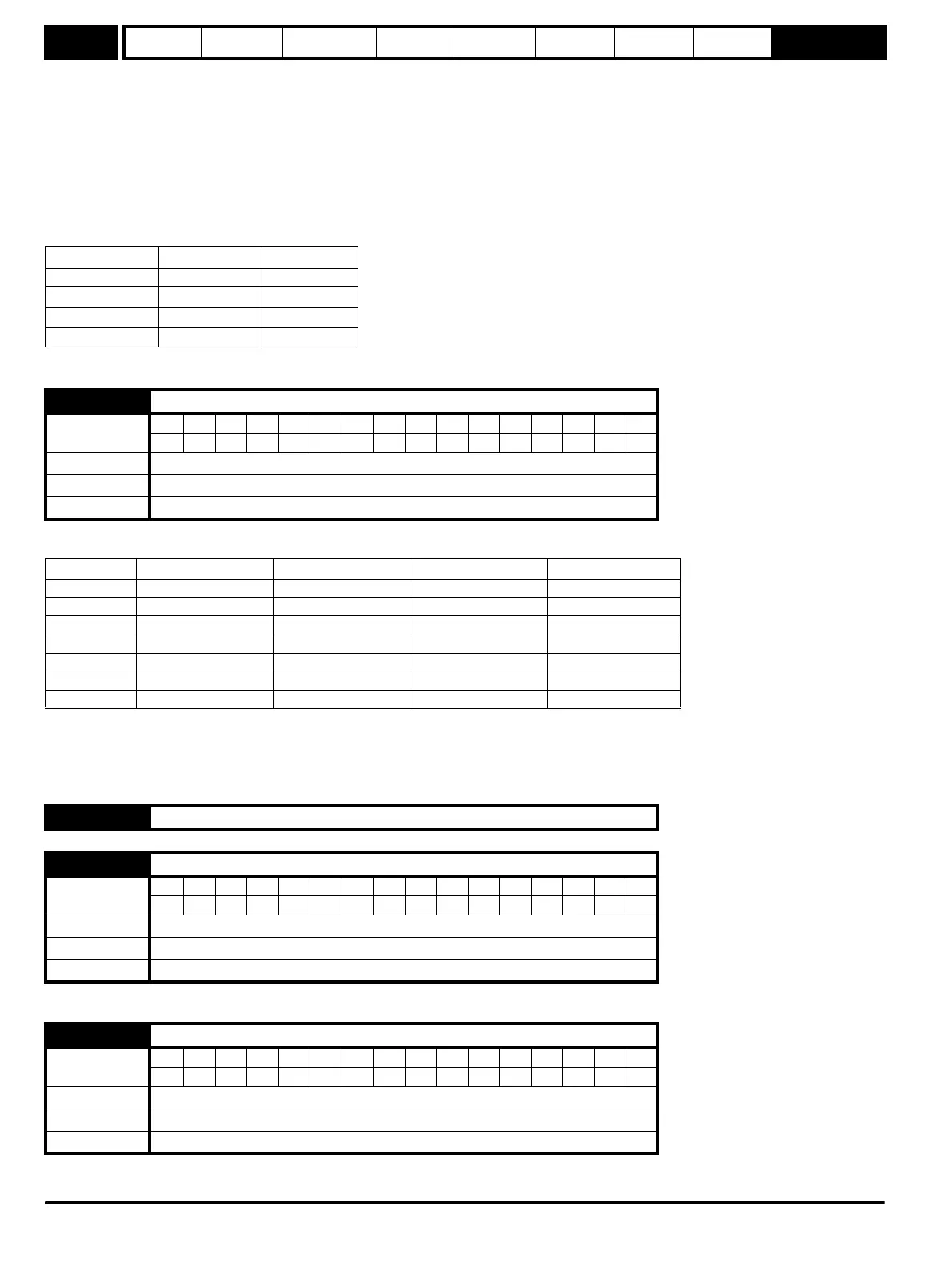
The following table shows the voltage levels used by drives with each voltage rating.
When the drive is carrying out a mains loss stop or ride through, the drive’s left hand display will show ‘AC’.
This parameter changes the functions of terminals B4, B5 and B6, which are normally associated with the enabling, starting and stopping the drive.
This also writes to parameter Pr 6.40 to enable and disable the input latches.
Pr 6.40, Pr 8.22, Pr 8.23 and Pr 8.24 are also saved when this parameter is modified.
A change to this parameter is only actioned when the drive is stopped, tripped or disabled. If the drive is active when this parameter is changed, the
parameter will return to its pre-altered value on exit of edit mode.
In mode 6 the user is free to assign the terminals as appropriate to their application.
Defines the current level used during DC injection braking as a percentage of rated active current as defined by Pr 5.07.
Defines the time of injection braking where this is specified in stopping modes 3 and 4 (see Pr 6.01 on page 69).
Voltage level 200V drive 400V drive
Vuu 175 330
Vml
1
205 410
Vml
2
195 390
VuuRestart 215 425
6.04 Start/stop logic select
Coding
Bit SP FI DE Txt VM DP ND RA NC NV PT US RW BU PS
1111
Range 0 to 6
Default EUR: 0, USA: 4
Update rate Actioned on exit of edit mode and on drive reset
Pr 6.04 Terminal B4 Terminal B5 Terminal B6 Pr 6.40
0 Enable Run Forward Run Reverse 0 (non latching)
1 Not Stop Run Forward Run Reverse 1 (latching)
2 Enable Run Fwd/Rev 0 (non latching)
3 Not Stop Run Fwd/Rev 1 (latching)
4 Not Stop Run Jog 1 (latching)
5 User programmable Run Forward Run Reverse 0 (non latching)
6 User programmable User programmable User programmable User programmable
6.05 Unused parameter
6.06 Injection braking level
Coding
Bit SP FI DE Txt VM DP ND RA NC NV PT US RW BU PS
11 111
Range 0.0 to 150.0 %
Default 100.0
Update rate Background
6.07 Injection braking time
Coding
Bit SP FI DE Txt VM DP ND RA NC NV PT US RW BU PS
1111
Range 0.0 to 25.0 s
Default 1.0
Update rate 2 ms