Introduction Parameter x.00
Parameter
description format
Keypad and
display
CT Modbus
RTU
User
programming
CT Soft Menu 0
Advanced parameter
descriptions
Menu 12
Commander SK Advanced User Guide 129
Issue Number: 2 www.controltechniques.com
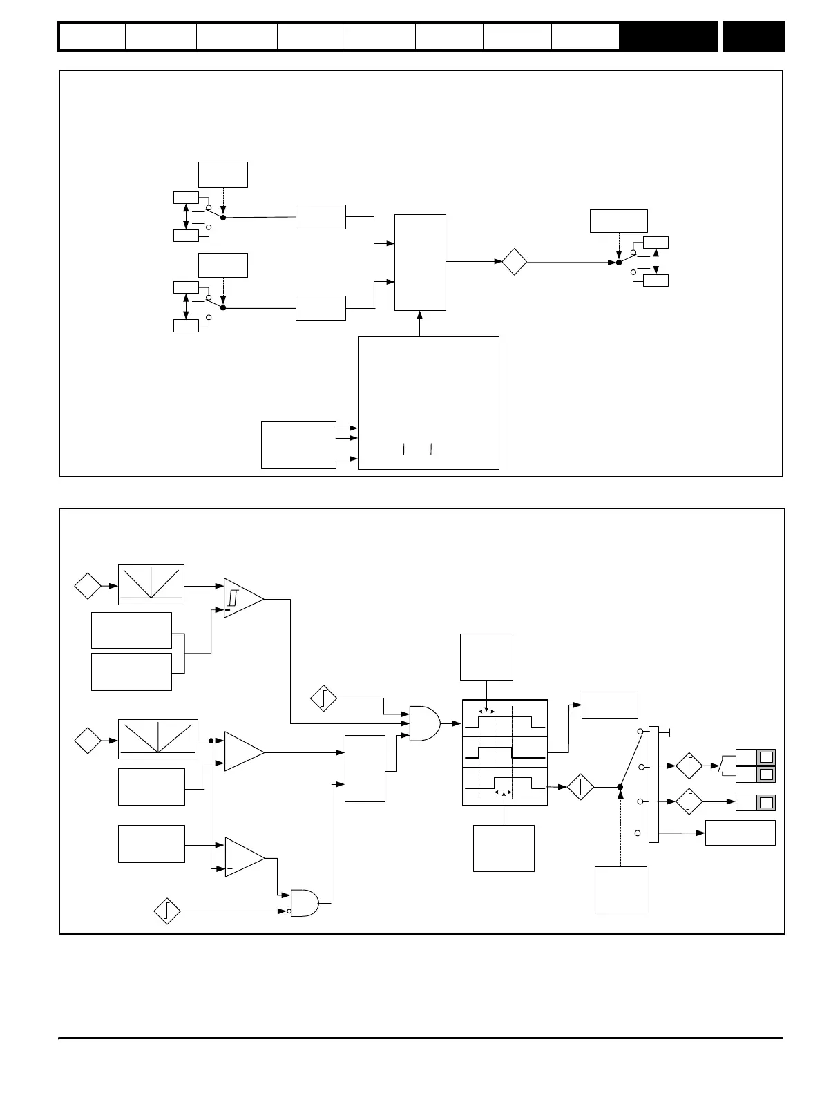
Figure 9-38 Menu 12C logic diagram
Figure 9-39 Menu 12D logic diagram
21.51
0.01
Source 2
12.29
21.51
0.01
Source 1
12.28
MENU 12C
Variable Selector 2
Scaling
12.33
Scaling
12.34
21.51
1.01
Destination
12.31
Output
12.32
%
Variable selector
control
12.35
Input 1
Input 2
Variable selector modes 12.30
0 - 12.32 = Input 1
1 - 12.32 = Input 2
2 - 12.32 = Input 1 + Input 2
3 - 12.32 = Input 1 - Input 2
4 - 12.32 = (Input 1 x Input 2) / 100
5 - 12.32 = (Input 1 x 100) / Input 2
6 - 12.32 = Input 1 / (12.35s + 1)
7 - 12.32 = Input 1 via Ramp
8 - 12.32 = Input 1
9 - 12.32 = Input 1
12.35
Current
magnitude
Brake release
current threshold
12.42
Brake applied
current threshold
12.43
Output
frequency
Brake release
frequency
12.44
+
+
Brake apply
frequency
12.45
Reference on
Drive active
+
&
In
Reset
Out
Latch
&
4.01
5.01
1.11
10.02
Brake release
Pre-brake
release
delay
12.46
Post-brake
release delay
12.47
Ramp hold
2.03
Brake
controller
enable
12.41
B3
0
1
2
3
T5
T6
User
Programmable
Brake disabled
8.07
8.01
12.40
MENU 12D
Mechanical Brake Function