Introduction Parameter x.00
Parameter
description format
Keypad and
display
CT Modbus
RTU
User
programming
CT Soft Menu 0
Advanced parameter
descriptions
Menu 15
Commander SK Advanced User Guide 149
Issue Number: 2 www.controltechniques.com
SM-I/O Lite & SM-I/O Timer
The Commander SK SM-I/O Lite & SM-I/O Timer options has an analog input that operates with 11 bit resolution in both voltage and current modes.
The analog output has a resolution of approximately 13 bits (
± 1.25mV resolution in voltage mode and ± 2.5µA resolution in current mode).
Sample time/Update rate
The sample time/update rate of the parameters controlled by a destination or read by a source will be 2ms plus 2ms times the number of destinations
or sources set up. For example, if only 2 digital inputs destinations are set-up, the parameters will be updated every 6ms. The software will cycle
through the background read parameter in the 2ms slot.
Encoder Input
The encoder input hardware is not a true quadrature input and may lose counts during direction change. The maximum input frequency is 55kHz
Error Codes
The following parameters are available when an I/O option module is fitted to the drive.
If the I/O options analog input is programmed in any of the modes 2 to 5 (see Pr 15.38) then this bit is set if the current input falls below 3mA. This bit
can be designated to a digital output to indicate that the current input is less then 3mA.
The digital inputs are set-up in positive logic only. This logic cannot be changed.
0 inactive
1 active.
These parameters indicate the state of the digital input terminals.
Terminals T5 to T7 are three programmable digital inputs.
If an external trip is required, then one of the terminals should be programmed to control the external trip parameter (Pr 10.32), with the invert set to a
1 so that the terminal must be made active for the drive not to trip.
0: de-energised
1: energised
This parameter indicates the state of the drive's status relay
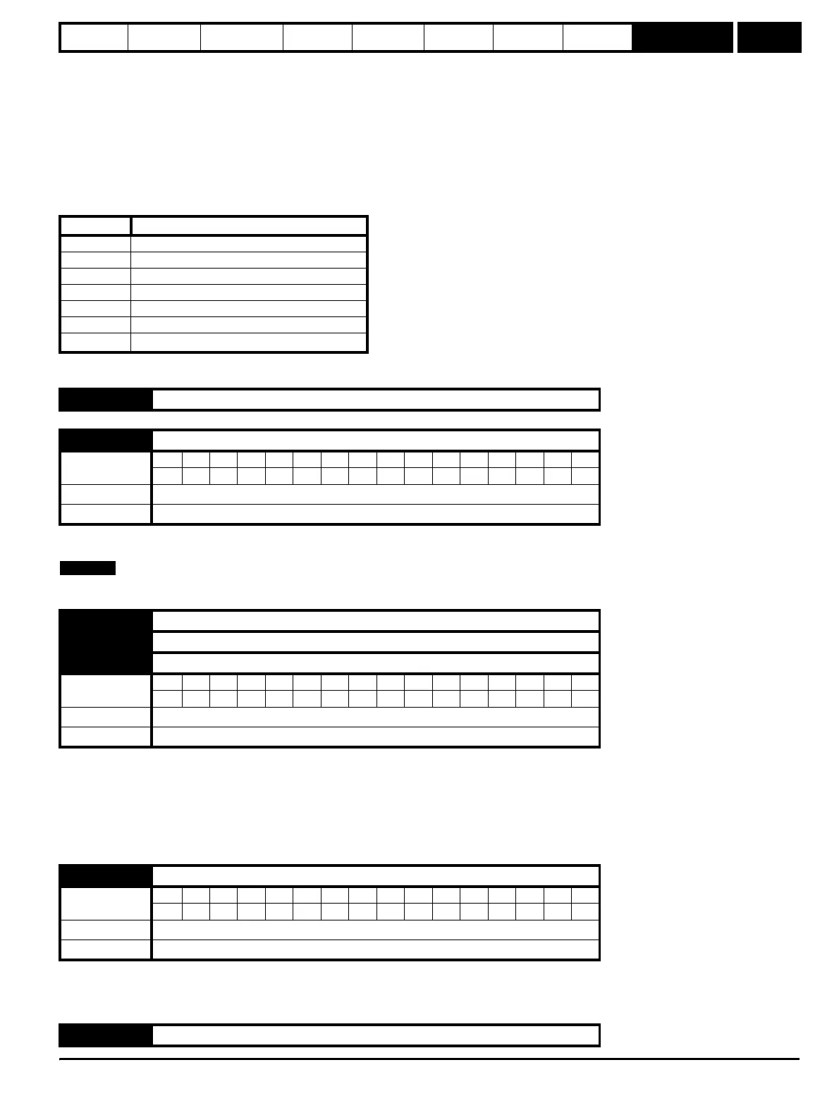
Error Code Reason for Fault
0 No error
1 Digital output short circuit
2 Current input too high or too low
3 Encoder supply over current
4 I/O module serial communications error
5 Real time clock error
74
I/O option PCB over temperature (>70
o
C)
15.01 to 15.02 Unused parameters
15.03 Current loop loss indicator
Coding
Bit SP FI DE Txt VM DP ND RA NC NV PT US RW BU PS
1111
Range 0 or 1
Update rate Background write
15.04 Terminal T5 digital input state
15.05 Terminal T6 digital input state
15.06 Terminal T7 digital input state
Coding
Bit SP FI DE Txt VM DP ND RA NC NV PT US RW BU PS
1111
Range 0 or 1
Update rate Background write
15.07 Relay state (Terminals T21 and T23)
Coding
Bit SP FI DE Txt VM DP ND RA NC NV PT US RW BU PS
1111
Range 0 or 1
Update rate Background write
15.08 to 15.13 Unused parameters
NOTE