Introduction Parameter x.00
Parameter
description format
Keypad and
display
CT Modbus
RTU
User
programming
CT Soft Menu 0
Advanced parameter
descriptions
Menu 6
Commander SK Advanced User Guide 69
Issue Number: 2 www.controltechniques.com
0: Coast stop
1: Ramp stop
2: Ramp stop + 1 second dc injection
3: Injection braking stop with detection of zero speed
4: Timed injection braking stop
Stopping is in two distinct phases: decelerating to stop, and stopped.
Once modes 3 or 4 have begun the drive must go through the ready state before being restarted either by stopping, tripping or being disabled.
This parameter has 3 settings as follows:
0diS
There is no mains loss detection and the drive operates normally only as long as the DC bus voltage remains within specification (i.e. >Vuu). Once
the voltage falls below Vuu a UU trip occurs and this will reset itself if the voltage rises again above VuuRestart in the table below.
1StoP
The action taken by the drive is the same as for ride through mode, except the ramp down rate is at least as fast as the deceleration ramp setting and
the drive will continue to decelerate to 0Hz even if the mains is re-applied.
Depending on whether the mains is re-applied during the ramp down phase will depend on what happens next:
• If the mains is not re-applied during the ramp down phase, the drive will trip on UU after it has reached 0Hz.
• If the mains is re-applied during the ramp down phase, when the drive reaches 0Hz and depending on the state of the control terminals, the drive
will either go into the 'rd' ready state or the drive will run back up to set speed.
Normally the controlling system will see that the mains has been lost and even though it has been re-applied, the controller will remove the run
terminal so that when it reaches 0Hz, it will go into the 'rd' state.
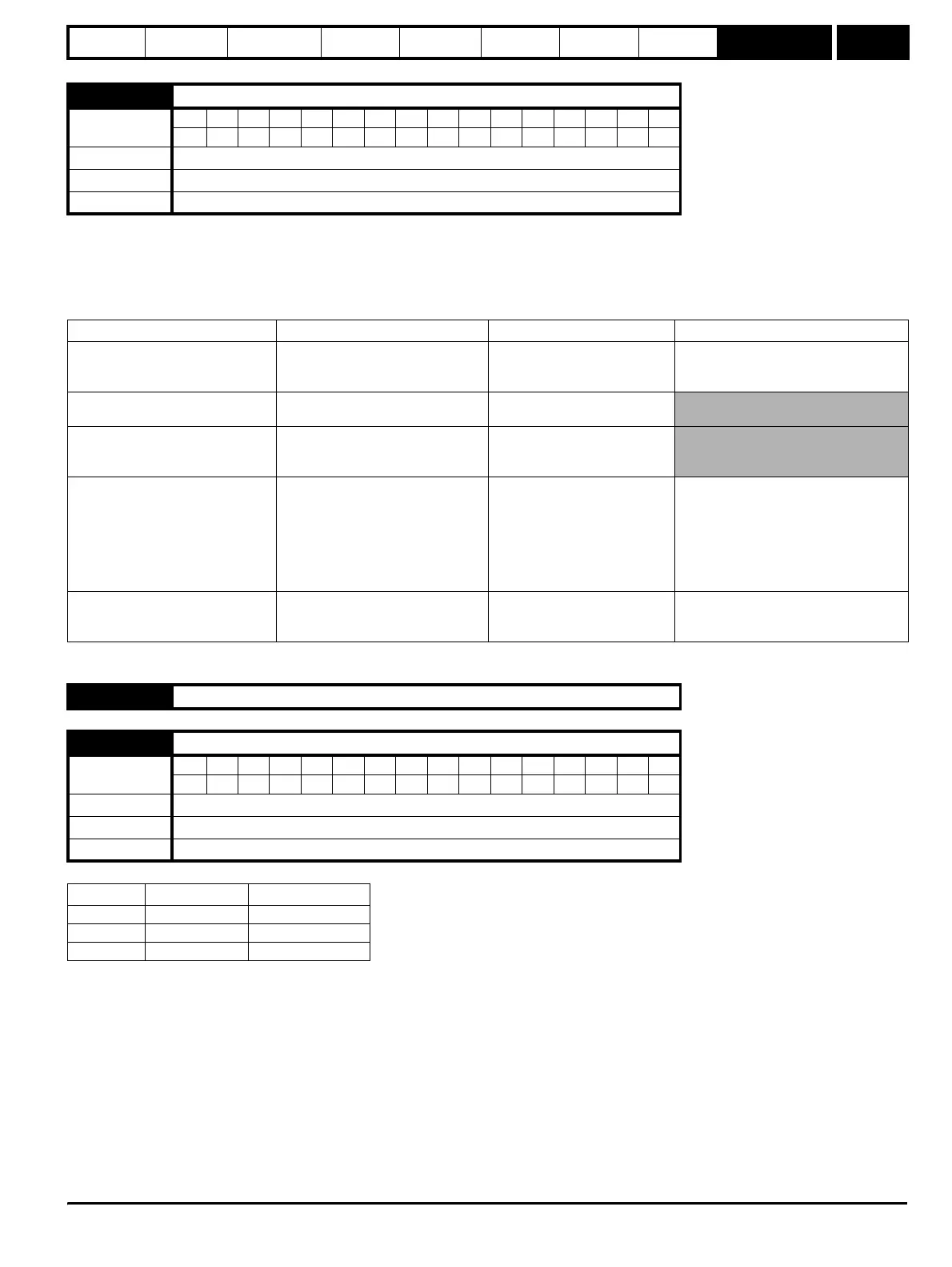
6.01 Stop mode
Coding
Bit SP FI DE Txt VM DP ND RA NC NV PT US RW BU PS
111
Range 0 to 4
Default 1
Update rate 2 ms
Stopping Mode Phase 1 Phase 2 Comments
0: Coast Inverter disabled
Drive cannot be re-enabled for
a specific time period which is
drive size dependant.
Delay in phase 2 allows rotor flux to
decay.
1: Ramp Ramp down to zero frequency
Wait for 1s with inverter
enabled
2: Ramp followed by DC injection Ramp down to zero frequency
Inject DC at level specified by
Pr 6.06 for time defined by
Pr 6.07
3: DC injection with zero speed
detection
Low frequency current injection with
detection of low speed before next
phase
Inject DC at level specified by
Pr 6.06 for time defined by
Pr 6.07
The drive automatically senses low
speed and therefore it adjusts the
injection time to suit the application. If
the injection current level is too small
the drive will not sense low speed
(normally a minimum of 50-60% is
required).
4: Timed DC injection braking stop
Inject DC at level specified by
Pr 6.06 for time specified by Pr 6.07
Inject DC at level specified by
Pr 6.06 for 1s
The minimum total injection time is 1s
for phase 1 and 1s for phase 2, i.e. 2s
in total.
6.02 Unused parameter
6.03 Mains loss mode
Coding
Bit SP FI DE Txt VM DP ND RA NC NV PT US RW BU PS
1 111
Range 0 to 2
Default 0
Update rate 2 ms
Pr 6.03 Mnemonic Function
0 diS Disabled
1 StoP Stop
2 rd.th Ride through