Menu 10 Introduction Parameter x.00
Parameter
description format
Keypad and
display
CT Modbus
RTU
User
programming
CT Soft Menu 0
Advanced parameter
descriptions
110 Commander SK Advanced User Guide
www.controltechniques.com Issue Number: 2
3. When the drive is first powered up a UU trip is initiated if the supply voltage is below the restart voltage level. This does not save power down
save parameters. If another trip occurs during power-up it is the active trip in preference to the UU trip. If this trip is cleared and the supply voltage
is still below the restart voltage threshold a UU trip is then initiated.
Table 9-16 Alarm Warnings
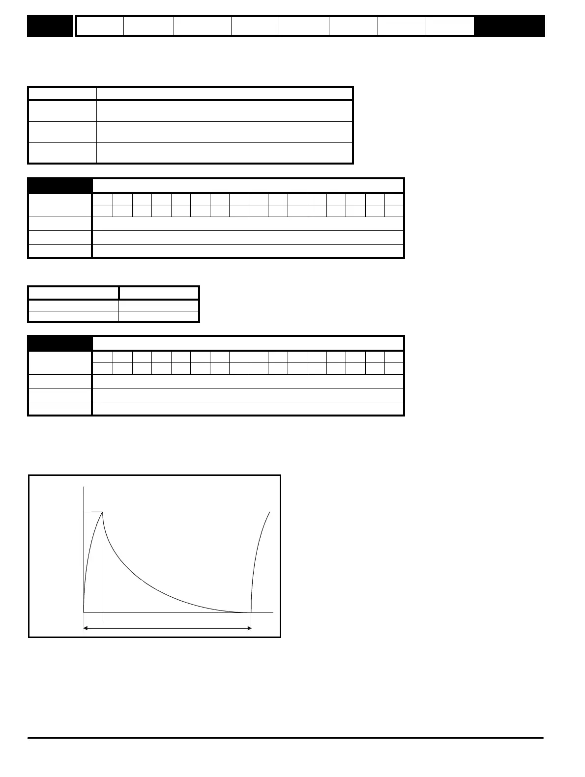
This parameter defines the time period that the braking resistor fitted can stand full braking volts without damage. The setting of this parameter is
used in determining the braking overload time.
This parameter defines the time period which must elapse between consecutive braking periods of maximum braking power as defined by Pr 10.30.
The setting of this parameter is used in determining the thermal time constant of the resistor fitted. It is assumed that the temperature will fall by 99%
in this time, and so the time constant is Pr 10.30 / 5. If either Pr 10.30 or Pr 10.31 are is set to 0 then no braking resistor protection is implemented.
The braking resistor temperature is modelled by the drive as shown below. The temperature rises in proportion to the power flowing into the resistor
and falls in proportion to the difference between the resistor temperature and ambient.
Assuming that the full power braking time is much shorter than the full power braking period (which is normally the case) the values for Pr 10.30 and
Pr 10.31 can be calculated as follows:
Power flowing into the resistor when the braking IGBT is on, Pon = Full braking volts
2
/ R
Where:
Full braking volts is defined in the table (see Pr 10.30) and R is the resistance of the braking resistor.
Full power braking time (Pr 10.30), T
on
= E / P
on
Where:
E is the total energy that can be absorbed by the resistor when its initial temperature is ambient temperature.
Display Condition
OVL.d
Ixt overload (see Pr 4.15, Pr 4.16 on page 51, Pr 4.19 on page 53 and
Pr 10.17 on page 107)
hot
Heatsink/IGBT temperature too high (see Pr 5.18 on page 63, Pr 5.35 on
page 65 and Pr 10.18 on page 107)
br.rS
Ixt overload on braking resistor (see Pr 10.12 on page 106, Pr 10.30 and
Pr 10.31)
10.30 Full power braking time
Coding
Bit SP FI DE Txt VM DP ND RA NC NV PT US RW BU PS
2111
Range 0.00 to 320.00 s
Default 0.00
Update rate Background
Drive voltage rating Full braking volts
200V 390V
400V 780V
10.31 Full power braking period
Coding
Bit SP FI DE Txt VM DP ND RA NC NV PT US RW BU PS
1111
Range 0.0 to 1500.0 s
Default 0.0
Update rate Background
0
100
%
t
Pr
10.30
Pr
10.31
Overload
accumulator
Pr
10.39