Menu 4 Introduction Parameter x.00
Parameter
description format
Keypad and
display
CT Modbus
RTU
User
programming
CT Soft Menu 0
Advanced parameter
descriptions
48 Commander SK Advanced User Guide
www.controltechniques.com Issue Number: 2
calculate the rated active and magnetising currents. The user may enter the nameplate values in Pr 5.07 and Pr 5.10 respectively and the drive will
operate satisfactorily. Alternatively the drive can perform an auto-tune test on the motor to measure the power factor at rated load by measuring R
s
(stationary test), σL
s
(stationary test), and L
s
(rotating test). See Pr 5.12 on page 60 for details.
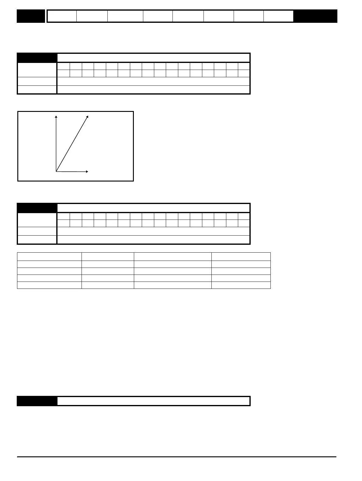
This parameter is the r.m.s. current from each output phase of the drive. The phase currents consist of an active component and a reactive
component. The three phase currents can be combined to form a resultant current vector as shown below:
The resultant current magnitude is displayed by this parameter. The active current is the torque producing current, and the reactive current is the
magnetising or flux producing current.
The active current is the torque producing current in a motor drive.
The diagram above shows the magnetising and active current vectors. These are represented in x and y axes of a reference frame. Pr 4.02 gives the
active current which is proportional to the length of the vector in the y axis and equivalent to the active phase current value in amps.
If the drive operates with fixed boost the y axis is aligned with the output voltage. Therefore the magnetising current represents the reactive
component of current leaving the drive and the active current represents the real component of current leaving the drive. Therefore the active current
produces torque and supplies the losses in the motor.
If the drive operates in vector mode (see Pr 5.14 on page 62) the x axis is aligned with the stator flux in the steady state, and so the active current
should be proportional to the torque produced by the machine. The active current will give a good indication of the machine torque over most of the
frequency range, however, the accuracy is reduced below 10Hz.
In both cases the relationship between the active current and motor torque will change once the maximum drive output voltage or the rated voltage of
the motor set by Pr 5.09 is reached, whichever is the lowest. (Generally the maximum drive output voltage will be just below the r.m.s. line supply
voltage.) Once one of these limits is reached the voltage is held constant and the motor flux reduces with frequency. This is referred to as field
weakening or constant power operation. In this region the relationship between torque and active current is approximately as follows, where K is a
constant related to the motor:
Torque = K x active current x frequency at voltage limit / actual frequency
Normally the point at which the voltage limit is reached is close to the rated frequency of the motor.
4.01 Current magnitude (motor current)
Coding
Bit SP FI DE Txt VM DP ND RA NC NV PT US RW BU PS
1 12111 1
Range 0 to DRIVE_CURRENT_MAX
Update rate Background
4.02 Motor active current
Coding
Bit SP FI DE Txt VM DP ND RA NC NV PT US RW BU PS
1 12111
Range ±DRIVE_CURRENT_MAX A
Update rate Background
Direction of active current Direction of rotation State and direction of rotation Torque
+ + Forward accelerating Motoring (+)
- + Forward decelerating or braking Regeneration (-)
+ - Reverse decelerating or braking Regeneration (-)
- - Reverse accelerating Motoring (+)
4.03 Unused parameter
Resultant
output current
Pr
4.01
Reactive current
Pr
4.17
y
x
ctive current
Pr
4.02