Introduction Parameter x.00
Parameter
description format
Keypad and
display
CT Modbus
RTU
User
programming
CT Soft Menu 0
Advanced parameter
descriptions
Menu 4
Commander SK Advanced User Guide 47
Issue Number: 2 www.controltechniques.com
On the larger Commander SK frame sizes, the ratio between maximum continuous current and maximum overload is less than on the smaller drives.
This is handled in the software by specifying the 'drives rated current' as maximum current limit level / 1.5, the same as on the smaller drives. The
current rating in Pr 11.32 is still the Heavy Duty rating of the drive, but because it is greater than the 'drive rating' figure used by the software, the
current limit point will be less than 150% of the rating specified in Pr 11.32.
The motor rated current (Pr 5.07) may be increased above the drive current rating specified in Pr 11.32 up to a limit defined by the Maximum motor
rated current. If the motor rated current is above the current rating specified in Pr 11.32, the motor thermal protection scheme is modified (see
Pr 4.16).
In the following descriptions the term 'drive rated current' is the one used by the software, not the value in Pr 11.32.
The drive has a current controller to give current limiting in frequency control mode and a torque controller in torque control mode. The active current
is controlled by modification of the drive output frequency. Menu 4 provides parameters to set-up the current controller. Additional voltage based
current control is provided to limit transients (peak-limit), but there are no user parameters to control this.
The drive operates in the stator flux reference frame under steady state conditions. The absolute maximum motor current is defined by the peak limit
system as 1.75 x rated drive current. However, the drive does not normally operate at this level, but uses the peak limit system as protection against
over-current trips. Under normal operation the motor current is limited to 1.50 x rated drive current, allowing a safety margin between the maximum
normal operating current and the peak limit level.
DRIVE_CURRENT_MAX is full scale current feedback, i.e. rated drive current x 2.0.
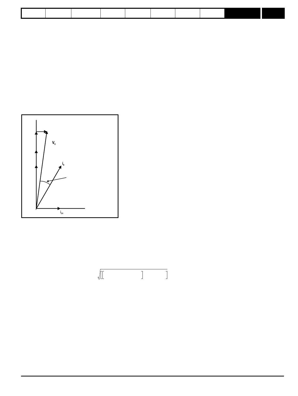
The relationship between the voltage and current is shown in the following vector diagram.
Definitions:
v
s
= motor terminal voltage vector
i
s
= motor current vector
i
sy
= y axis component of current
i
sx
= x axis component of current
v* = no load y axis voltage reference
MOTOR1_CURRENT_LIMIT_MAX is used as the maximum for some parameters such as the user current limits. This is defined in the vector
equation as follows (with a maximum of 1000%):
Where:
Motor rated current is given by Pr 5.07
PF is motor rated power factor given by Pr 5.10
(MOTOR2_CURRENT_LIMIT_MAX is calculated from the motor map 2 parameters)
The Maximum current is either (1.5 x Rated drive current) when the rated current set by Pr 5.07 (or Pr 21.07 if motor map 2 is selected) is less
than or equal to the Maximum Heavy Duty current rating, otherwise it is (1.1 x Maximum motor rated current).
For example, with a motor of the same rating as the drive and a power factor of 0.85, the maximum current limit is 165.2%.
The above calculation is based on the assumption that the flux producing current (Pr 4.17) in the stator flux reference frame does not vary with load
and remains at the level for rated load. This is not the case and the flux producing current will vary as the load is increased. Therefore the maximum
current limit may not be reached before the drive reduces the current limit to prevent the peak limit from becoming active.
The rated active and rated magnetising currents are calculated from the power factor (Pr 5.10) and motor rated current (Pr 5.07) as:
rated active current = power factor x motor rated current
rated magnetising current = √(1 - power factor
2
) x motor rated current
The drive uses the motor rated current and the power factor at rated load to set up the maximum current limits, scale the current limits correctly and
v*
Stator flux
in stead
state
ϕ ≈
cos (PF)
-1
Ri
ssx
Ri
ssy
i
sy
MOTOR1_CURRENT_LIMIT_MAX
Maximum current
Motor rated current
-------------------------------------------------------
2
PF()
2
1–+
PF
--------------------------------------------------------------------------------------------------------
100%×=