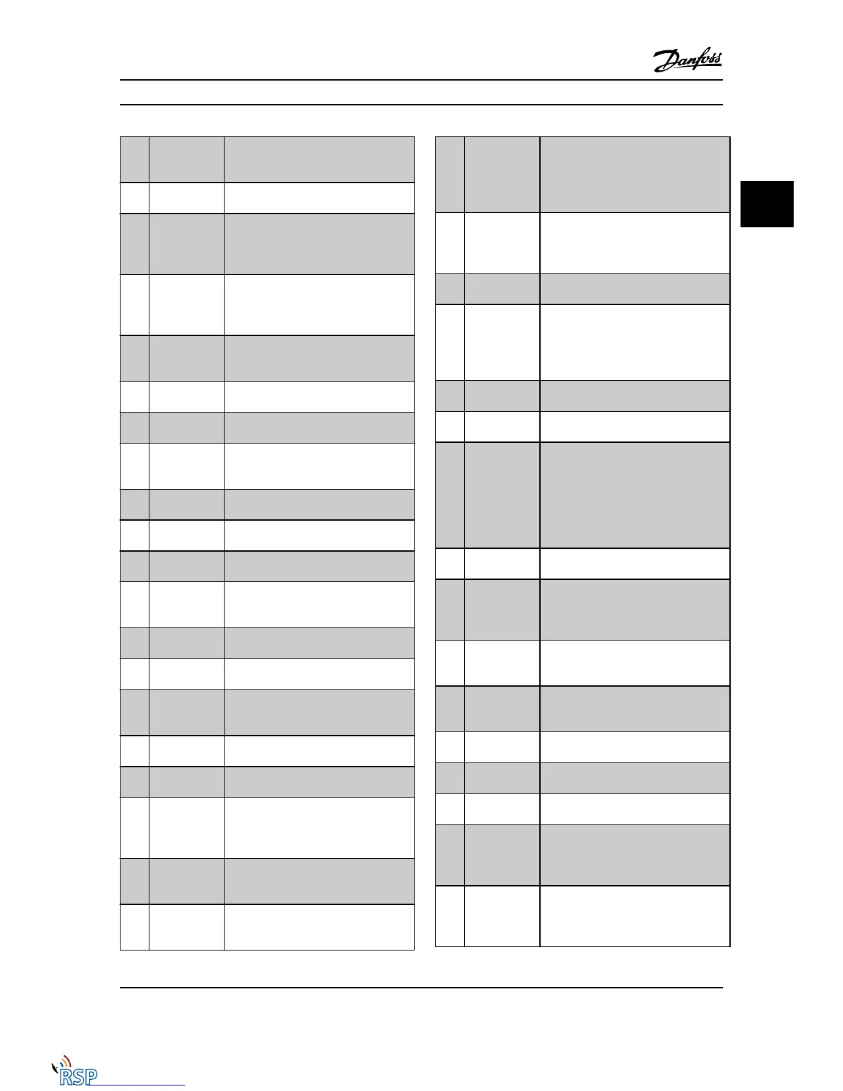
[4] Enable / no
warning
Ready for operation. No start or stop
command is been given (start/disable).
No warnings are active.
[5] VLT running Motor is running and shaft torque is
present.
[6] Running / no
warning
Output speed is higher than the speed
set in 1-81 Min Speed for Function at Stop
[RPM]. The motor is running and there are
no warnings.
[7] Run in
range/no
warning
Motor is running within the programmed
current and speed ranges set in
4-50 Warning Current Low to 4-53 Warning
Speed High. There are no warnings.
[8] Run on
reference / no
warning
Motor runs at reference speed. No
warnings.
[9] Alarm An alarm activates the output. There are
no warnings.
[10] Alarm or
warning
An alarm or a warning activates the
output.
[11] At torque limit
The torque limit set in 4-16 Torque Limit
Motor Mode or 4-17 Torque Limit Generator
Mode has been exceeded.
[12] Out of current
range
The motor current is outside the range
set in 4-18 Current Limit.
[13] Below current,
low
Motor current is lower than set in
4-50 Warning Current Low.
[14] Above current,
high
Motor current is higher than set in
4-51 Warning Current High.
[15] Out of speed
range
Output frequency is outside the
frequency ranges set in 4-52 Warning
Speed Low and 4-53 Warning Speed High.
[16] Below speed,
low
Output speed is lower than the setting in
4-52 Warning Speed Low.
[17] Above speed,
high
Output speed is higher than the setting
in 4-53 Warning Speed High.
[18] Out of
feedback range
Feedback is outside the range set in
4-56 Warning Feedback Low and
4-57 Warning Feedback High.
[19] Below
feedback low
Feedback is below the limit set in
4-56 Warning Feedback Low.
[20] Above
feedback high
Feedback is above the limit set in
4-57 Warning Feedback High.
[21] Thermal
warning
The thermal warning turns on when the
temperature exceeds the limit in the
motor, the Adjustable frequency drive,
the brake resistor, or the thermistor.
[22] Ready, no
thermal
warning
Adjustable frequency drive is ready for
operation and there is no over-
temperature warning.
[23] Remote, ready,
no thermal
warning
Adjustable frequency drive is ready for
operation and is in [Auto on] mode.
There is no over-temperature warning.
[24] Ready, voltage
OK
Adjustable frequency drive is ready for
operation and the AC line voltage is
within the specified voltage range (see
General Specifications section in the
Design Guide).
[25] Reverse
Reversing. Logic ‘1’ when CW rotation of
the motor. Logic ‘0’ when CCW rotation
of the motor. If the motor is not rotating,
the output will follow the reference.
[26] Bus OK Active communication (no timeout) via
the serial communication port.
[27] Torque limit
and stop
Use in performing a coasting stop and in
torque limit condition. If the Adjustable
frequency drive has received a stop signal
and is at the torque limit, the signal is
Logic ‘0’.
[28] Brake, no brake
warning
Brake is active and there are no warnings.
[29] Brake ready, no
fault
Brake is ready for operation and there are
no faults.
[30] Brake fault
(IGBT)
Output is Logic ‘1’ when the brake IGBT is
short-circuited. Use this function to
protect the Adjustable frequency drive if
there is a fault on the brake modules. Use
the output/relay to cut out the AC line
voltage from the Adjustable frequency
drive.
[31] Relay 123 The relay is activated when Control Word
[0] is selected in parameter group 8-**.
[32] Mechanical
brake control
Enables control of an external mechanical
brake, see description in the section
Control of Mechanical Brake, and
parameter group 2-2*
[33] Safe stop
activated (FC
302 only)
Indicates that the safe stop on terminal
37 has been activated.
[40] Out of ref
range
Active when the actual speed is outside
settings in 4-52 Warning Speed Low to
4-55 Warning Reference High.
[41] Below
reference low
Active when actual speed is below speed
reference setting.
[42] Above
reference high
Active when actual speed is above speed
reference setting
[43] Extended PID
Limit
[45] Bus Ctrl Controls output via bus. The state of the
output is set in 5-90 Digital & Relay Bus
Control. The output state is retained in
the event of bus timeout.
[46] Bus Ctrl On at
timeout
Controls output via bus. The state of the
output is set in 5-90 Digital & Relay Bus
Control. In the event of a bus timeout,
the output state is set high (On).
Parameter Descriptions FC 300 Programming Guide
MG33MD22 - VLT
®
is a registered Danfoss trademark 3-55
3
3

 Loading...


