[47] Bus Ctrl Off at
timeout
Controls output via bus. The state of the
output is set in 5-90 Digital & Relay Bus
Control. In the event of a bus timeout,
the output state is set low (Off).
[51] MCO controlled Active when a MCO 302 or MCO 305 is
connected. The output is controlled from
option.
[55] Pulse output
[60] Comparator 0 See parameter group 13-1*. If Comparator
0 is evaluated as TRUE, the output will go
high. Otherwise, it will be low.
[61] Comparator 1 See parameter group 13-1*. If Comparator
1 is evaluated as TRUE, the output will go
high. Otherwise, it will be low.
[62] Comparator 2 See parameter group 13-1*. If Comparator
2 is evaluated as TRUE, the output will go
high. Otherwise, it will be low.
[63] Comparator 3 See parameter group 13-1*. If Comparator
3 is evaluated as TRUE, the output will go
high. Otherwise, it will be low.
[64] Comparator 4 See parameter group 13-1*. If Comparator
4 is evaluated as TRUE, the output will go
high. Otherwise, it will be low.
[65] Comparator 5 See parameter group 13-1*. If Comparator
5 is evaluated as TRUE, the output will go
high. Otherwise, it will be low.
[70] Logic Rule 0 See parameter group 13-4*. If Logic Rule
0 is evaluated as TRUE, the output will go
high. Otherwise, it will be low.
[71] Logic Rule 1 See parameter group 13-4*. If Logic Rule
1 is evaluated as TRUE, the output will go
high. Otherwise, it will be low.
[72] Logic Rule 2 See parameter group 13-4*. If Logic Rule
2 is evaluated as TRUE, the output will go
high. Otherwise, it will be low.
[73] Logic Rule 3 See parameter group 13-4*. If Logic Rule
3 is evaluated as TRUE, the output will go
high. Otherwise, it will be low.
[74] Logic Rule 4 See parameter group 13-4*. If Logic Rule
4 is evaluated as TRUE, the output will go
high. Otherwise, it will be low.
[75] Logic Rule 5 See parameter group 13-4*. If Logic Rule
5 is evaluated as TRUE, the output will go
high. Otherwise, it will be low.
[80] SL Digital
Output A
See 13-52 SL Controller Action. The output
will go high whenever the Smart Logic
Action [38] Set dig. out. A high is
executed. The output will go low
whenever the Smart Logic Action [32] Set
dig. out. A low is executed.
[81] SL Digital
Output B
See 13-52 SL Controller Action. The input
will go high whenever the Smart Logic
Action [39] Set dig. out. A high is
executed. The input will go low whenever
the Smart Logic Action [33] Set dig. out. A
low is executed.
[82] SL Digital
Output C
See 13-52 SL Controller Action. The input
will go high whenever the Smart Logic
Action [40] Set dig. out. A high is
executed. The input will go low whenever
the Smart Logic Action [34] Set dig. out. A
low is executed.
[83] SL Digital
Output D
See 13-52 SL Controller Action. The input
will go high whenever the Smart Logic
Action [41] Set dig. out. A high is
executed. The input will go low whenever
the Smart Logic Action [35] Set dig. out. A
low is executed.
[84] SL Digital
Output E
See 13-52 SL Controller Action. The input
will go high whenever the Smart Logic
Action [42] Set dig. out. A high is
executed. The input will go low whenever
the Smart Logic Action [36] Set dig. out. A
low is executed.
[85] SL Digital
Output F
See 13-52 SL Controller Action. The input
will go high whenever the Smart Logic
Action [43] Set dig. out. A high is
executed. The input will go low whenever
the Smart Logic Action [37] Set dig. out. A
low is executed.
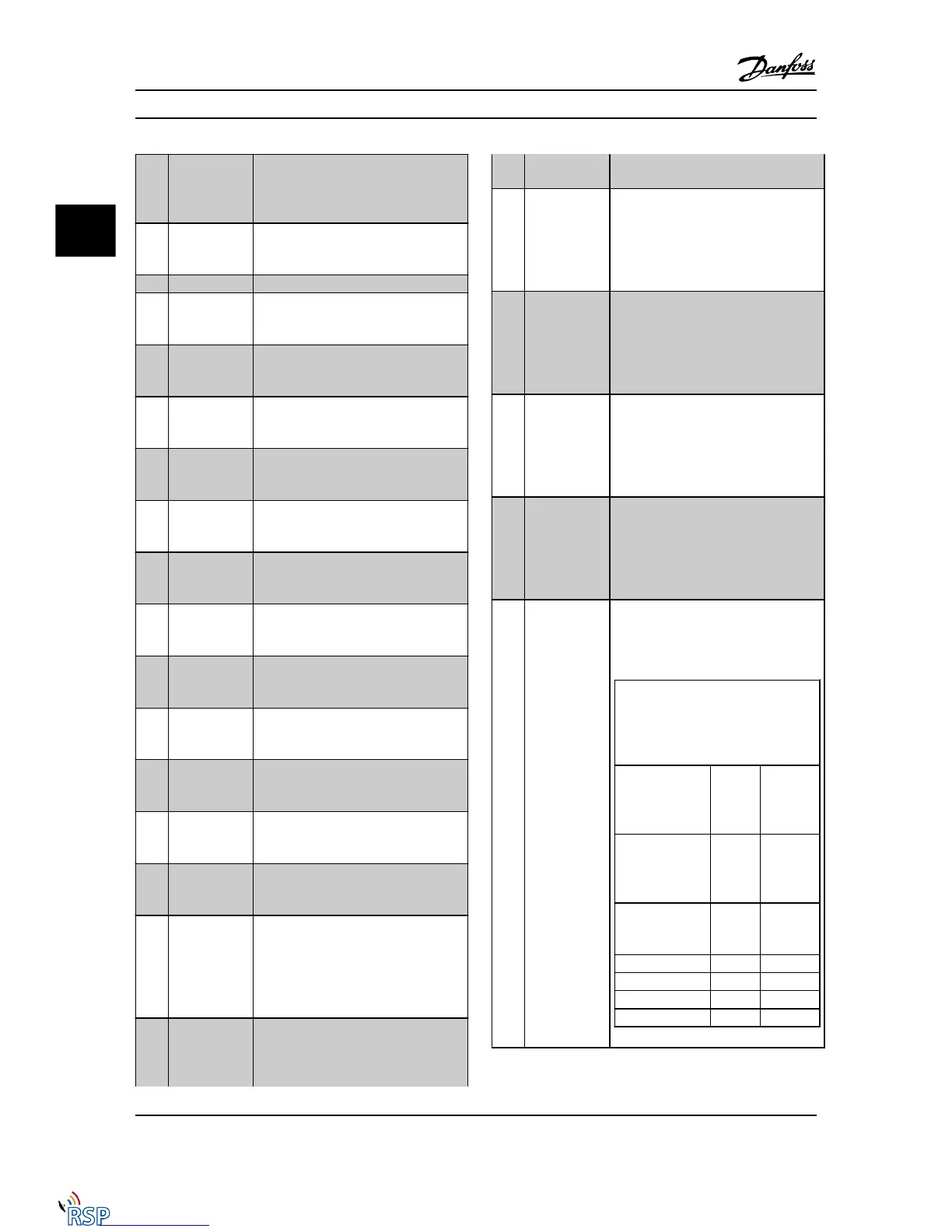
[120] Local reference
active
Output is high when 3-13 Reference Site =
[2] Local or when 3-13 Reference Site = [0]
Linked to hand auto at the same time as
the LCP is in [Hand on] mode.
Reference site
set in
3-13 Reference
Site
Local
referenc
e
active
[120]
Remote
reference
active
[121]
Reference site:
Local
3-13 Reference Site
[2]
1 0
Reference site:
Remote
3-13 Reference Site
[1]
0 1
Reference site:
Linked to Hand/
Auto
Hand 1 0
Hand -> off 1 0
Auto -> off 0 0
Auto 0 1
Parameter Descriptions FC 300 Programming Guide
3-56 MG33MD22 - VLT
®
is a registered Danfoss trademark
3
3

 Loading...


