Chapter 7 High-speed Counter Module AH02HC/AH04HC
7-15
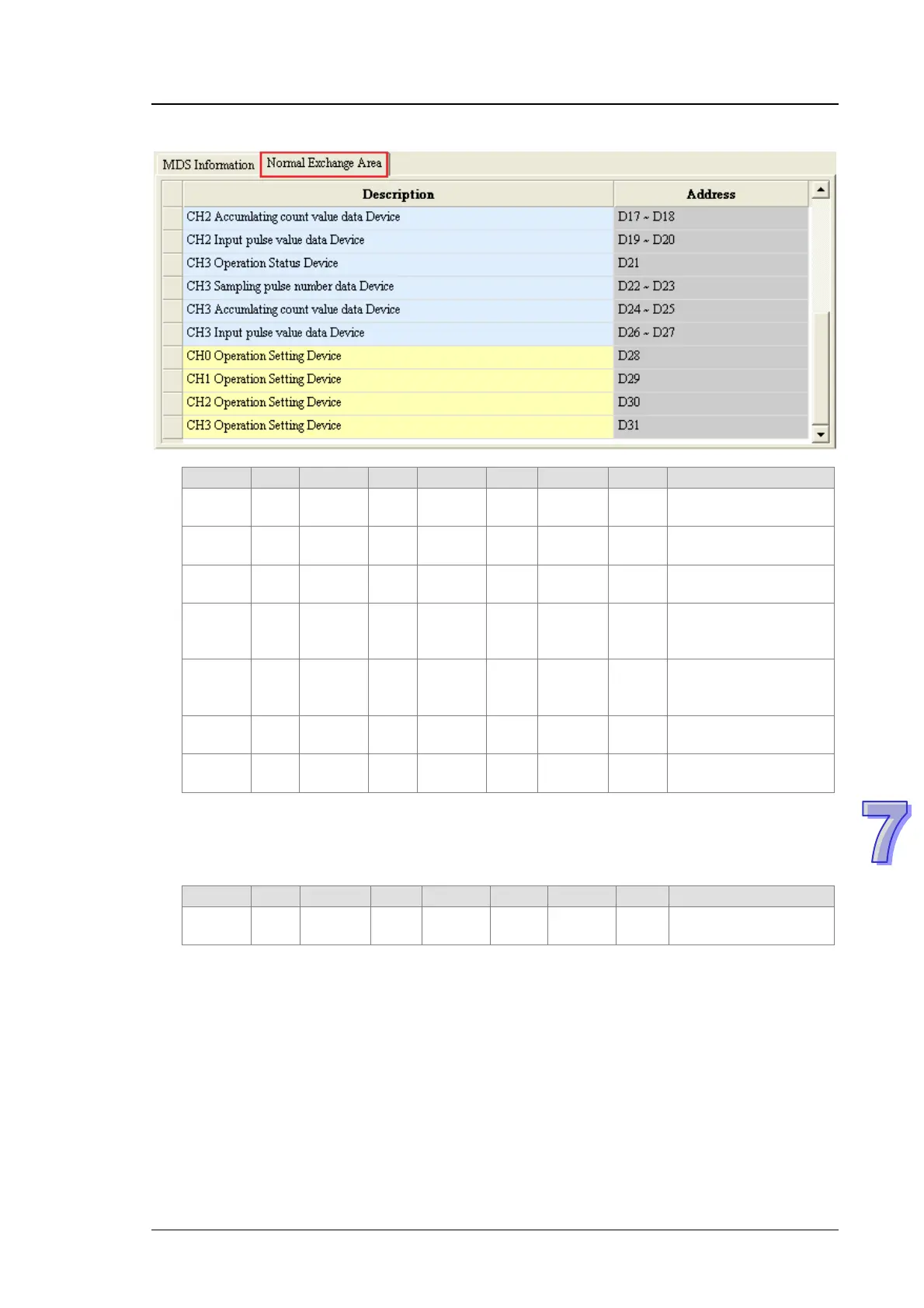
Input devices
Register CH0 Register CH1 Register CH2 Register CH3 Parameter
D0 #19 D7 #47 D14 #75 D21 #103
Operating state of a
counter
D1 #20 D8 #48 D15 #76 D22 #104
Number of sampled
pulses (Low word)
D2 #21 D9 #49 D16 #77 D23 #105
Number of sampled
pulses (high word)
D3 #22 D10 #50 D17 #78 D24 #106
Number of
accumulated pulses
(Low word)
D4 #23 D11 #51 D18 #79 D25 #107
Number of
accumulated pulses
(High word)
D5 #24 D12 #52 D19 #80 D26 #108
Number of input pulses
(Low word)
D6 #25 D13 #53 D20 #81 D27 #109
Number of input pulses
(High word)
Users can monitor the operation of AH04HC-5A by means of a monitoring table. In the figure
below, the parameters corresponding to D0~D27 are monitored.
Output devices
Register CH0 Register CH1 Register CH2 Register CH3 Parameter
D28 #0 D29 #28 D30 #56 D31 #84
Operation of a counter
(*1)
*1: CR0, CR28, CR56, and CR84 can only be used as normal exchange registers. They can not
be set by means of the instruction TO.