Chapter 8 Serial Communication Module AH10/15SCM
8-5
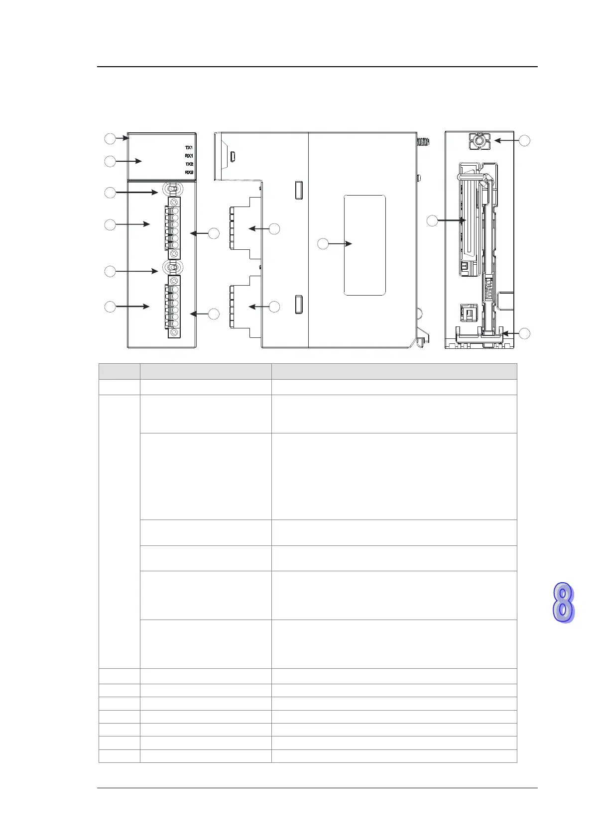
8.2.2 Profile
AH10SCM-5A
10SCM
COM 1
TX-
TX+
TR 1 O N O FF
CO M2 RS4 85
CO M1 RS4 85
RUN
ERROR
FE
SG
FE
SG
O FFO NTR 2
COM 2
TX+
RX+
RX-
TX-
D+
D-
FE
SG
RX-
FE
SG
D-
D+RX+
1
12
2
3
4
7
13
6
8
9
11
10
5
9
Number
Name Description
1 Model name Model name of the module
2
RUN LED indicator (green)
Operating status of the module
ON: The module is running.
OFF: The module stops running.
ERROR LED indicator (red)
Error status of the module
ON: There is a hardware error.
OFF: The module is normal.
Blink: 1. The setting of the module is incorrect, or there
is a communication error.
2. Restoring the module to the default factory
value
COM1 (RS-485) LED
indicator (green)
OFF: RS-422 mode
COM2 (RS-485) LED
indicator (green)
OFF: RS-422 mode
TX1/TX2 LED indicator
(orange)
Blink: The data is being transmitted through the
RS-485/RS422 port.
OFF: The data is not being transmitted through the
RS-485/RS422 port.
RX1/RX2 LED indicator
(orange)
Blink: The data is being reveived through the
RS-485/RS422 port.
OFF: The data is not being reveived through the
RS-485/RS422 port.
3 Switch of terminal resistor 1 Switching terminal resistor 1 ON/OFF
Terminals for COM1 (RS-422)
Terminals for COM1 (RS-485)
Switch of terminal resistor 2
Switching terminal resistor 2 ON/OFF
Terminals for COM2 (RS-422)
Terminals for COM2 (RS-485)
European-style terminal