Chapter 10 DeviceNet Communication Module AH10DNET
10-5
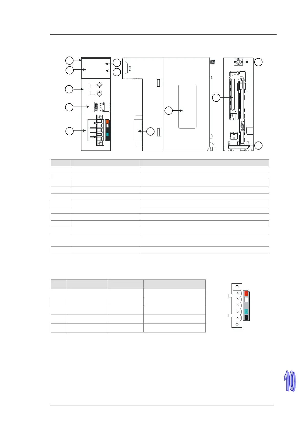
10.2.2 Parts
IN 1
IN 0
DR 1
DR 0
10DNET
NS
MS
N ode Addres s
x10
x10
1
0
5
4
3
2
1
0
9
8
7
6
5
4
3
2
1
0
9
8
7
6
1
2
3
4
7
6
8
9
10
5
12
11
4 Function switch For setting the function
DeviceNet connection port
9 Label Nameplate
11 Backplane interface
The connector is used to connect the module and the
backplane.
10.2.3 DeviceNet Communication Connector
The connector is used on the connection to DeviceNet. Wire by using the connector enclosed with
AH10DNET-5A.
Pin
Signal
Color
Description
5
V+ Red 24 V DC
4
CAN_H White Signal+
3
- - Shielded wire
2
CAN_L Blue Signal-
1
V- Black 0 V DC
Note:
1. Connect the 24 V DC network power supply between V+ and V-.
2. One 121 ohm terminal resistor may be needed to connect between white and blue signal wires.
For more details, please refer to section 10.3.4.