AH500 Module Manual
10-56
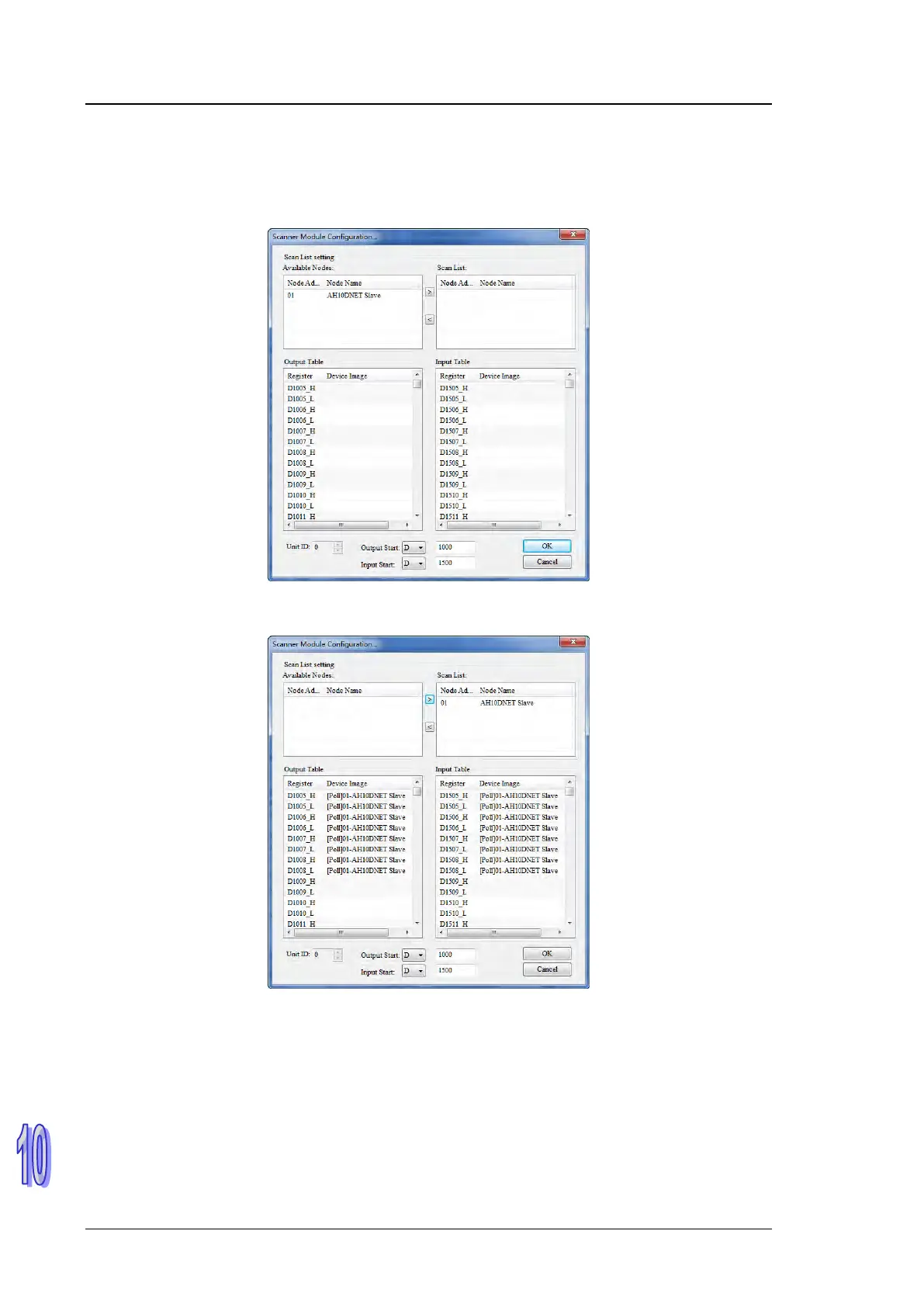
10.9.4 Configuring DeviceNet Slave into the Master
1. Double click AH10DNET Scanner (Node 1) on the main software interface and “Scanner
Module Configuration” dialog box appears, where see the currently available node AH10DNET
Slave in the left list.
2. Add the node device in “Available Nodes” to Scan List. In the example, the starting addresses
for output and input are D1500 and D1000 respectively.
Note:
(1) After the connection between the master and slave is built successfully, fill the control data
in the registers in “Output Table” and the data will be transmitted to the slave automatically.
(2) After the connection between the master and slave is built successfully, the data that slave
feedback will be transmitted to the registers in “Input Table”.
(3) The registers in “Output Table” are specified by “Output Start”.
(4) The registers in “Input Table” are specified by “Input Start”.
3. Click “OK” after confirming that no error exists to download the configuration to AH10DNET-5A.
If the AH500 series CPU module is in run mode during downloading, the warning dialogue box
will pop up as below.