AH500 Module Manual
7-28
7. Bit 6 in CR4/CR32/CR60/CR88: If bit 6 in CR4/CR32/CR60/CR88 is turned OFF, ≧ is selected.
If bit 6 in CR4/CR32/CR60/CR88 is turned ON, ≦ is selected. Before users select a type of
comparison condition, bit 5 in CR4/CR32/CR60/CR88 must be turned ON.
8. Bit 7 in CR4/CR32/CR60/CR88: After bit 7 in CR4/CR32/CR60/CR88 is turned OFF,
AH04HC-5A will not output any hardware signal if the number of accumulated pulses meets the
comparison condition set. After bit 7 in CR4/CR32/CR60/CR88 is turned ON, AH04HC-5A will
output a hardware signal if the number of accumulated pulses meets the comparison condition
set. Before users setting bit 7 in CR4/CR32/CR60/CR88, bit 5 in CR4/CR32/CR60/CR88 must
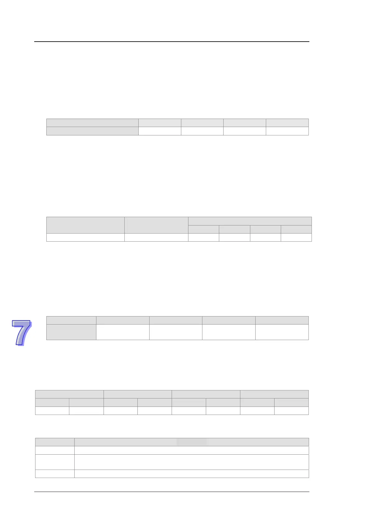
be turned ON. The related hardware signals are described below.
Item CH0 CH1 CH2 CH3
Hardware signal
Y0.8 Y0.9 Y0.10 Y0.11
9. Bit 8 in CR4/CR32/CR60/CR88:
After bit 8 in CR4/CR32/CR60/CR88 is turned OFF, AH04HC-5A will not send a message
which asks the CPU module to execute the interrupt subroutine specified to the CPU
module if bit 3 in CR19/CR47/CR75/CR103 is turned from OFF to ON.
After bit 8 in CR4/CR32/CR60/CR88 is turned ON, AH04HC-5A will immediately send a
message which asks the CPU module to execute the interrupt subroutine specified to the
CPU module if bit 3 in CR19/CR47/CR75/CR103 is turned from OFF to ON. Bit 5 in
CR4/CR32/CR60/CR88 needs to be turned ON before bit 8 in CR4/CR32/CR60/CR88 is
turned ON.
The related parameter is described below.
Item Value/Setting value
Parameter
CH0 CH1 CH2 CH3
Interrupt number 0~31 #18 #46 #74 #102
10. Bit 9 in CR4/CR32/CR60/CR88:
After bit 9 in CR4/CR32/CR60/CR88 is turned OFF, the number of sampled pulses, the
number of accumulated pulses, and the number of input pulses will not be cleared if X0.0+
and X0.0–/X0.1+ and X0.1–/X0.2+ and X0.2–/X0.3+ and X0.3– are turned ON.
After bit 9 in CR4/CR32/CR60/CR88 is turned ON, the number of sampled pulses, the
number of accumulated pulses, and the number of input pulses will be cleared if the
external signals X0.0+ and X0.0–/X0.1+ and X0.1–/X0.2+ and X0.2–/X0.3+ and X0.3– are
turned ON.
The related parameter is described below.
Item CH0 CH1 CH2 CH3
External
signal
X0.0+ and X0.0– X0.1+ and X0.1– X0.2+ and X0.2– X0.3+ and X0.3–
11. Bit 10 in CR4/CR32/CR60/CR88: If bit 10 in CR4/CR32/CR60/CR88 is turned ON, the input
contact of the external signal is a normally-closed contact. If bit 10 in CR4/CR32/CR60/CR88 is
turned OFF, the input contact of the external signal is a normally-open contact.
7.9.6 Operating State of a Counter
CH0 CH1 CH2 CH3
High word Low word High word Low word High word Low word High word Low word
- #19 - #47 - #75 - #103
[Description]
Bit 0~bit 15 are described below.
bit# Described
0 The setting of the counting function is complete.
1
The linear accumulation is larger than the maximum value or less than the minimum
value.
2 The circular accumulation is equal to the maximum value or the minimum value.