Chapter 12 Network Module AH10PFBM
12-5
12.2.4 Seven-segment Display
The digital display could provide the following functions:
Displaying the node address and error information of AH10PFBM-5A
Displaying the error information of the slave
Notes:
The digital display shows its node address when AH10PFBM-5A works normally.
It indicates that the E2 error exists in the slave of node address 03 if E2 and 03 appear
continuously.
Please follow the instruction in section 12.7.2 if the common error such as E2, F2 and etc
exists.
12.3 Installation
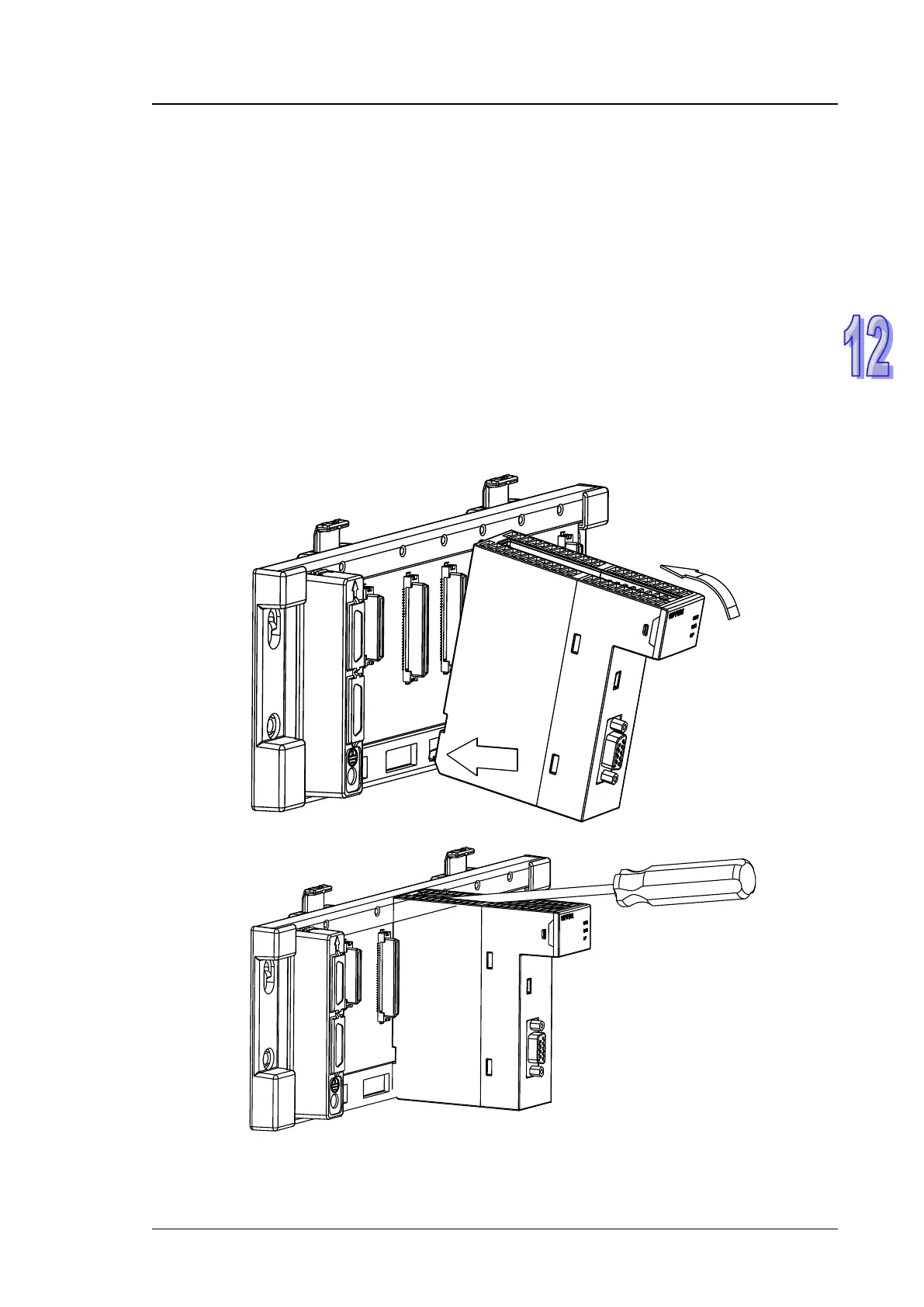
12.3.1 Installing AH10PFBM -5A and PLC CPU to the Main Rack
1. Insert the projection under the module into the hole in the rack;
2. Push the module in the direction indicated by the following arrow to meet the IO slot of the rack.
3. After properly installing, tighten the screw on the upper of the module.