AH500 Module Manual
5-54
temperature sensor, On+ and In+ have to be short-circuited, and On- and In- have to be
short-circuited. (n is in the range of 0 to 7.)
*2. If users want to measure the resistance in the range of 0 Ω to 300 Ω, they can use a two-wire
or three-wire sensor instead of a four-wire sensor.
*3. User need to select an appropriate sensor. If a Ni100 temperature sensor, a Pt100 sensor,
and a resistance sensor are used, the internal excitation current is 471.5 μA. If a Ni1000
temperature sensor, and a Pt1000 temperature sensor are used, the internal excitation
current is 204.8 μA.
5.2.10 LED Indicators
1
RUN LED
indicator
Operating status of the module
ON: The module is running.
OFF: The module stops running.
2
ERROR LED
indicator
Error status of the module
ON: A serious error occurs in the module.
OFF: The module is normal.
Blink: A slight error occurs in the module.
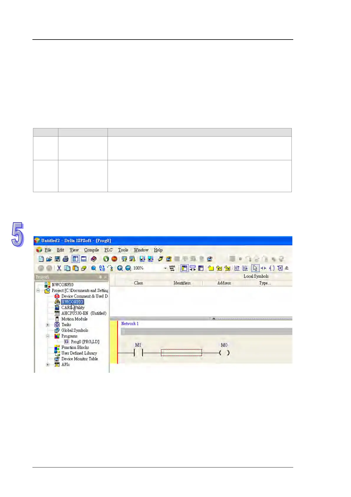
5.2.11 HWCONFIG in ISPSoft
5.2.11.1 Initial Setting
(1) Start ISPSoft, and then double-click HWCONFIG.