AH500 Module Manual
10-18
10.6 Network Node Status Display
10.6.1 Scan List Node Status Display
The function is used for monitoring whether the DeviceNet slave is offline or not. The scanner
module conducts the real-time monitor and control of the nodes in the scan list and maps the status
of each node in the scan list to one bit so that users could acquire the status information of the
network node through monitoring the value in the corresponding register.
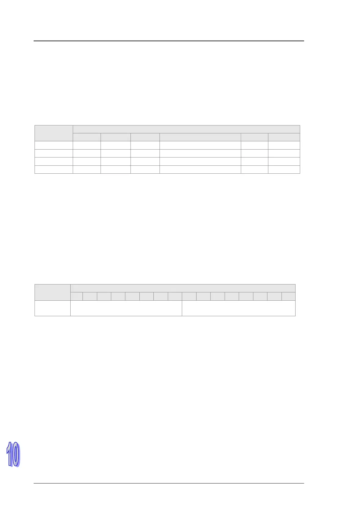
If the starting address for the input is D1000, the corresponding relations between the node status
registers and the slave are as follows.
Node status
register
Corresponding network node
Node 15 Node 14 Node 13
… … Node 1 Node 0
Note: If the starting address for the input is set to D567 (See section 10.6.2), the node status
registers are D567~D570 instead of D1000~D1003.
When the nodes in the scan list are normal, the corresponding bit is OFF; when the nodes are
abnormal, the corresponding bit is ON.
10.6.2 Scanner Module Status Display
If the starting address for the input is D1000, users could acquire the status message of the scanner
module AH10DNET-5A through monitoring D1004 in real time.
When the scanner module works normally, the content of D1004 is 0; when the scanner module is
initializing, the content of the high byte and low byte in D1004 are 1 and 0 respectively; when an
error occurs in the scanner module, the high byte content in D1004 is 2 and the low byte content is
the error code.
Regarding the details on the error code, please refer to the seven-segment display in section
10.10.2.
register
D1004
(0: Normal, 1: Initializing, 2: Error)
Error codes in the scanner module
(See section 7.11.2.)
Note: If the starting address for the input is set to D600 (Refer to section 10.6.2), the register in the
above table is D604 instead of D1004.

 Loading...


