AH500 Module Manual
12-52
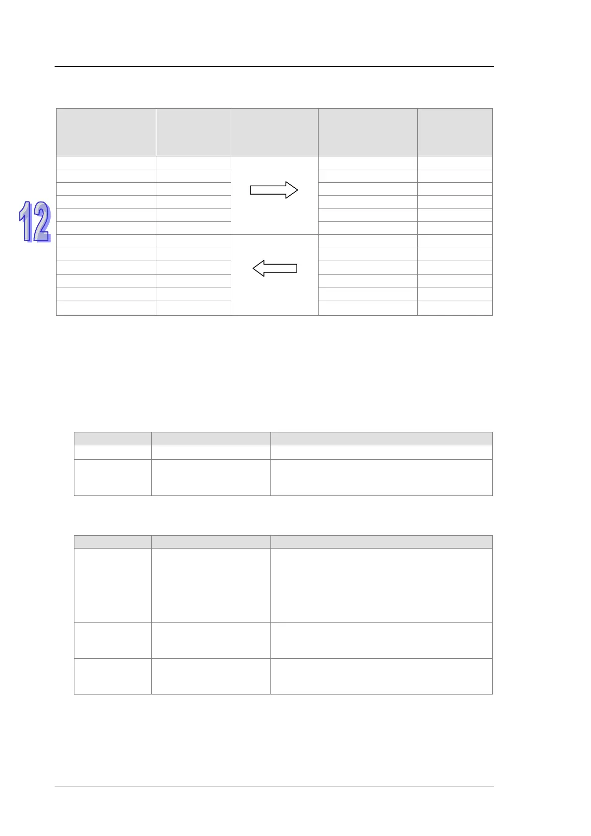
After the master establishes the communication with the slave, the data in registers D of the master
and slave for exchange are shown as the following table.
Register in master
PLC
Value
(Decimal)
transmitted
through
PROFIBUS
Register in slave
PLC
Value
(Decimal)
D6002 502 D302 502
D1001 101 D201 101
D1005 105 D501 105
12.7 LED Indicator and Trouble-shooting
AH10PFBM-5A provides 6 kinds of diagnosis methods such as the indicators, digital displays,
registers in normal exchange area, ISPSoft software, registers in input area, SYCON.net software.
12.7.1 Indicators
RUN LED
RUN LED displays the status of PLC CPU on the left of AH10PFBM-5A.
Green light on PLC is in RUN status.
--
Off PLC is in STOP status.
Turn the RUN/STOP switch of AH PLC to RUN
or check if the hardware configuration in AH
PLC is consistent with that in the actual rack.
SYS LED
SYS LED displays if the internal hardware or firmware of AH10PFBM-5A is normal.
Green light on
After power on, the red
light flickers once, which
indicates the firmware is
initializing and then
green light is on
constantly.
--
Red light
flickers
firmware in the master
fails
Contact the factory if the error still exists after
re-powering 10PFBM.
Red light on
firmware in the master
fails
Contact the factory if the error still exists after
re-powering 10PFBM.